Could someone please verify my proposal.
I have already assembled with 24 Volt relays similar to the turn on delay circuit. I am perhaps unnecessarily concerned about the resistive bridge between channels. My idea is to bypass one relay and use two boards one for each channel so back to 24 volt power and no resistive connection between channels.
While I think that should work I’m also now realizing that I was intending to use this in a balanced bridge output amplifier so do I need to break both leads to each speaker? If so is there any reason not to replace the relays with DPDT 12 volt so all connections could be broken to both speakers with a single board?
Unsure of relay spec I need
Hello,
I'm new to electronics, so I've found figuring out what kind of power supply to use and how to match the relays to the power source confusing, so I'm not sure if I understand this correctly.
I gather that the relay has to be sized for both the power source used to power the protection board and the power output of the amplifier that you are protecting the speakers from. I'll be using this for an F6 (and probably other first watt amplifiers in the future)
I'm going to use a 400va power supply for the amplifier (antek 4218 transformer), which is rated a 18v + 18v (36v). If I wanted to
power the board from the 4218 transformer, I would pull power from only one side and I would use the two 12vdc relays from the 24v version, correct?
If I decided to power the board from a separate transformer I could use the antek 0124 transformer or equivalent and use the same 12vdc relays.
I definitely am not sure how to make sure this is sufficient for my amplifiers output power (f6, powered by the antek 4218 transformer). Would using
the 12v relays rated for 10 amps be enough?
Thanks, Jim
I'm going to use a 400va power supply for the amplifier (antek 4218 transformer), which is rated a 18v + 18v (36v). If I wanted to
power the board from the 4218 transformer, I would pull power from only one side and I would use the two 12vdc relays from the 24v version, correct?
I am also using a 36v transformer and need 24v for the speaker protector.
Have you come up with a solution?
Thanks
In searching and reading this thread I found there is also a thread for the previous version of the board which has useful information. I found that you can power the board with dc from your power supply. No changes are necessary, though you can leave out the rectifying diodes and the filter capacitor. In my case my power supply provides 24v+ and 24v-, so my protection board was set up with relays for 24v. The V2 thread mentions connecting your + to the protection board + terminal and your ground to the protection board - terminal.
Unfortunately I can't confirm how well this works, as a long period of time passed between finding this out and hooking up the protection board in my amp. I hooked up the protection board with 24v+ and 24v- instead of using my power supply ground. This caused some smoke to come from one of the resistors and damaged some other components. Rather than fiddle with a bunch of damaged parts I am just going to rebuild the board, as it is inexpensive. I'll let you know how it works out when I get complete the second board. For now my F6 will not have speaker protection . I do have concerns that my power supply will be slightly unbalanced from having power for the protection board coming from only one side. I am guessing that I will not be able to hear a difference.
Unfortunately I can't confirm how well this works, as a long period of time passed between finding this out and hooking up the protection board in my amp. I hooked up the protection board with 24v+ and 24v- instead of using my power supply ground. This caused some smoke to come from one of the resistors and damaged some other components. Rather than fiddle with a bunch of damaged parts I am just going to rebuild the board, as it is inexpensive. I'll let you know how it works out when I get complete the second board. For now my F6 will not have speaker protection . I do have concerns that my power supply will be slightly unbalanced from having power for the protection board coming from only one side. I am guessing that I will not be able to hear a difference.
Does anyone know if this speaker protection board shorts to ground in the event of a failed relay?
Trying to understand how these tiny relays can protect an amp sufficiently?
Rod Elliot documents this approach in Loudspeaker Protection and Muting
I can't really tell from the schematic if it goes to ground or is just open?
Trying to understand how these tiny relays can protect an amp sufficiently?
Rod Elliot documents this approach in Loudspeaker Protection and Muting
I can't really tell from the schematic if it goes to ground or is just open?
Does anyone know if this speaker protection board shorts to ground in the event of a failed relay?
Trying to understand how these tiny relays can protect an amp sufficiently?
Rod Elliot documents this approach in Loudspeaker Protection and Muting
I can't really tell from the schematic if it goes to ground or is just open?
It appears to me the relays open the circuit between amp and speakers in the event of detecting DC at the amplifier output.
It appears to me the relays open the circuit between amp and speakers in the event of detecting DC at the amplifier output.
What are the parameters of the DC detection feature ?
I tested this feature with no detectable outcome.
Do you or anyone else know the DC treshold is Q5 or this protection board reacts to? (I went all the way up to 9V-100mA of DC on the output with no reaction)
What are the parameters of the DC detection feature ?
I tested this feature with no detectable outcome.
Do you or anyone else know the DC treshold is Q5 or this protection board reacts to? (I went all the way up to 9V-100mA of DC on the output with no reaction)
My first suspicion was that amplifier ground and speaker negative output were not connected so after i confirmed this, (happens when protection board is as it should powered by a different transformer/winding/supply) i simply connected the utility power source negative with the main ground via a 10K resistor and enabled sensing.
The same approach would apply to balanced builds to enable sensing... you can imagine what happens if sensing is directly applied to balanced outputs

29 VAC on secondaries
Hi folks...I just finished building the speaker protect circuit using the 12VDC relays. The center tapped transformer I bought to power the circuit ( supposed to have been 12-0-12, TRIAD F-45X) measures 29VAC across the two outside secondaries. I tried it out anyway. The circuit’s LED did what they were supposed to do (wow what a rapid blinking) and the speaker input-outputs has continuity after the relays clicked on. My question is if the 29VAC will be too much for this circuit/relays over time and should I seek a slightly lower output transformer, say 24-26VAC?
Thanks! Pete
Hello Pete,
A 29V AC would go to 40V after rectification and a bit of filtering.
Maybe using a LM317 to bring down the utility rail to 24V would spare you the expense of another trafo.
Thanks, I will explore that..I measured 29VAC in (whether under the circuit load or not) and 17VDC across pins 2&5 of each of the relays. The stats sheet says the relay can handle 170% of max rated voltage so I’m assuming that means each relay can actually handle up to 20.4 VDC?
Their consumption is very low,
Would be better to power them with 11V not 17V for a reliable coil life
A regulator can fit on a wire if nicely shrink wrapped and even include a 200mA resetable fuse.
But hey if it works ... you have my 2 cents
I’m grateful for your input, really. Some questions though: so would this be an appropriate resettable fuse (mouser; 530-0ZRR0010FF1E)? For setting 24V out of the LM317 I could use 180R for R1 (between ADJ and Vout pins) and 3.3K for R2 (from ADJ to neutral/return wire of AC line)? Heat sink needed? Where would the resettable fuse be connected?
Thanks, Pete
Thanks, Pete
Their consumption is very low,
Would be better to power them with 11V not 17V for a reliable coil life
A regulator can fit on a wire if nicely shrink wrapped and even include a 200mA resetable fuse.
But hey if it works ... you have my 2 cents
I’m grateful for your input, really. Some questions though: so would this be an appropriate resettable fuse (mouser; 530-0ZRR0010FF1E)? For setting 24V out of the LM317 I could use 180R for R1 (between ADJ and Vout pins) and 3.3K for R2 (from ADJ to neutral/return wire of AC line)? Heat sink needed? Where would the resettable fuse be connected?
Thanks, Pete
The fuse protects the circuit from accidents si it can go a bit higher .. 500mA
It goes right after the transformer output .
The voltage regulator resistor values are good See here : LM317 Resistor and Voltage Calculator
It does not need sinking under 200mA or so the circuit draws.
So go nuts on the shrink tube and enjoy!
Please excuse the totally noob question. I completed the speaker protection board and went to test it. Power light - check. Blinking led - check. Blinking led goes solid and I can hear the relays latch - check.
But something still did not seem right. For my test I used a Zettler Magnetics BV301S24023 which is marked primary 115 VAC and secondary 24 VAC. Its a 2.3 VA transformer.
My line voltage in is 119 VAC but when I measured the voltage across the secondaries, I am getting 42 VAC. Which seemed kind of high. I measured the resistance of the primary coil and got .53 K ohm and 90.6 ohms across the secondary. This would suggest to me that my secondary voltage should be around 17% of my input voltage or about 20 volts. Again I am making a big assumption that the primaries and secondaries are using the same material for the windings.
What am I missing? Do I have a bum transformer?
Much appreciate any insights you could provide.
rsaumure: did you measure the secondary output while hooked up to the speaker protection circuit or w/o any load on the transformer? The BV301S24023 has a no load Vmax (41.9V) of about what you measured. Measure the VAC across the input at the Protection board while it’s on. When the transformer and the board are connected, and on, what VDC do you get across pins 2 & 5 of the relay itself? I presume you are using the 12V relays?
Pete
Pete
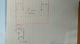
You must use either a dual secondary into dual rectifiers and then series connect the two smoothed outputs
Is this what you mean? Not sure I understand your explanation. As I understand for a dual secondary, both secondaries must be implied in the circuitery ?
Attachments
rsaumure: did you measure the secondary output while hooked up to the speaker protection circuit or w/o any load on the transformer? The BV301S24023 has a no load Vmax (41.9V) of about what you measured. Measure the VAC across the input at the Protection board while it’s on. When the transformer and the board are connected, and on, what VDC do you get across pins 2 & 5 of the relay itself? I presume you are using the 12V relays?
Pete
Cool - thanks I was measuring without any load on the secondaries. I am using the 12 V relays. Right now I am trying to figure out how to stuff everything into the 4U Deluxe chassis. Did nor realize how tight everything was going to be inasmuch as I built the Universal Power Supply all on one board. Need to go back and break off the diode sections. In practice when installing the speaker protection circuit I assume you just pull power directly from the toroidal transformer? Much thanks!
- Home
- The diyAudio Store
- Speaker Turn On Delay and DC Protector Board Set (V3)