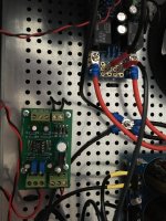
Have just assembled and carefully checked my DC protection board I was surprised to find C6 was overheating. I had installed it with the neg side inserted into the square pad side.
Turns out this side is positive! After removing the cap I measured the voltage on the pads. I checked my board against the image posted just above (Astromo). Has anyone else discovered this?
Turns out this side is positive! After removing the cap I measured the voltage on the pads. I checked my board against the image posted just above (Astromo). Has anyone else discovered this?
Have just assembled and carefully checked my DC protection board I was surprised to find C6 was overheating. I had installed it with the neg side inserted into the square pad side.
Turns out this side is positive! After removing the cap I measured the voltage on the pads. I checked my board against the image posted just above (Astromo). Has anyone else discovered this?
Having sorted that out with the relays operating normally, I find the pcb
is laid out to use the relay's bottom right contact - must be NC (viewing bottom of relay with coil connections on the lhs). My relay, Omron G5LE-1A4 has no contact in that position having just three in total.
Rod Elliott's writeup describing his P33 project offers some good information regarding the use of relays for speaker protection. One point, in particular, is using the NC relay contact to short the speaker to common (ground) when a fault occurs.
Thanks for that. Problem is I am 99% done. Just having a problem finding a relay which has the NO contact on bottom rhs (with relay bottom up).
It is this position which tracks through to the SPK1 and SPK2 terminals.
Update - I realise my error. I imagined it would be easier to troubleshoot if I populated the board on the opposite side to the component labelling so I could still read all of it. I figured it wouldn't matter but I see now that the relays are the only components that must be soldered to the same side as the labelling. You live and learn!
Last edited:
I am putting mine into an M2X, where can I tap off 24v AC from the PSU? or am I better using a separate transformer. Would 20VA be enough?
This question has been asked previously.
I found this response. Quote - a trafo of 10-15VA was recommended
There's only one place to tap ac voltage from the psu - off the transformer before rectification. However, I have 18vac transformers on my psu (dual mono)
For my speaker protection board I used Mouser part 553-VPL24-400. It's a 10VA 12/24vac transformer.
DC Protection Board not working with VU Meter
Hi diyAudio community,
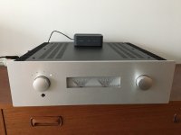
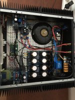
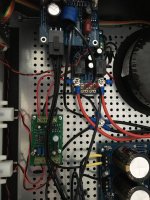
this is my first post in this Forum - so Hi! I have built an audio amp based on few diyAudioStore components (soft start, speaker protection board, universal power supply). I used LM3886 Done Right as amplifier. The transformer I used is 300VA 2x22 V. I also used a secondary transformer (18V) to power speaker protection board, source switch and VU meter board with AC. I do not have schematics yet, but I posted few photos to give an impression, the whole project is pretty straight forward.
My current problem is as soon as I connect signal output terminals and ground to the VU meter board, the speaker protection delay will not engage.
I measured the DC on the input terminals on DC protection board, in both cases (with and without vu meter connected) the voltage is ~0.004V.
Does anyone have an idea why the DC protection board might not kick in? Thank you.")
Hi diyAudio community,
this is my first post in this Forum - so Hi! I have built an audio amp based on few diyAudioStore components (soft start, speaker protection board, universal power supply). I used LM3886 Done Right as amplifier. The transformer I used is 300VA 2x22 V. I also used a secondary transformer (18V) to power speaker protection board, source switch and VU meter board with AC. I do not have schematics yet, but I posted few photos to give an impression, the whole project is pretty straight forward.
My current problem is as soon as I connect signal output terminals and ground to the VU meter board, the speaker protection delay will not engage.
I measured the DC on the input terminals on DC protection board, in both cases (with and without vu meter connected) the voltage is ~0.004V.
Does anyone have an idea why the DC protection board might not kick in? Thank you.
Attachments
Max ac voltage
Hello gentlemen,
I'm planning to build both the speaker protection and soft start boards.
quick question:
I will use a power transformer having 2x28 Vac secondary voltage output, is this voltage ok to supply the speaker protection borad or is it too high?
the relays will be the 12Vdc type (Panasonic JS1-12V-F)
thanks in advance for your help
Diego
Max ac voltage
Hello,
could someone be so kind to help me?
My question about the maximum ac voltage was driven by the fact that I have no room inside the chassis to put an additional transformer.
So, having 2x28Vac secondary output, will the relays survive?
The relays are 12Vdc coil type, so 24Vdc being in series
In case they would not be ok, I can switch to the 18Vdc coil type, wired in series.
thank you
have a good we
I have built one of these, and it was working just fine until recently.
It is in an F5Turbo. The DC offset at the speaker posts is 40 Volts. It tripped at that level earlier today. Since then, it no longer trips.
It flashes on power up.
You can hear the relays make when it senses no DC. However, when the capacitor bank is started, the amplifier sends 40 VDC through the speaker protection circuit without tripping.
What do you think has happened?
looks like a burnt output mosfet
full DC rail voltage to the speakers
Found the issue -- Drain and Source were being shorted on one Mosfet -- just did not see it.
Anyway:
Since the Speaker protector failed after tripping on about 36 VDC, can someone enlighten me on what needs to be repaired? The relay seems to work just fine. It just fails to open when DC is present.
Found the issue -- Drain and Source were being shorted on one Mosfet -- just did not see it.
Anyway:
Since the Speaker protector failed after tripping on about 36 VDC, can someone enlighten me on what needs to be repaired? The relay seems to work just fine. It just fails to open when DC is present.
Check ALL output mosfet, make sure no shorts are present.
Basically, there are NO electro-mechanical relays able to open a DC short circuit, the contacts generally remain stuck each other.
Your relay is very likely burnt (contacts heavily damaged), better to replace it.
- Home
- The diyAudio Store
- Speaker Turn On Delay and DC Protector Board Set (V3)