Hi, new member and first post, so be kind ")
I just built two of theese boards, one working fine, the other one however is only opening one relay.
I powered them from a 15VDC powersupply i had from before, using 12V relays that might be low, but the three other relays are working fine.
Now my skills in electronics are REALLY low all i could find out was that this relay got now power to the coil, and the Ohm was different over the last rectifier then all the other ones, so i swapped it for a new one.
Now i get power to the coil, but it still wont close...
I messed up my order for parts so i have double of everything except the relays, so my question is: can it be anything else than a faulty relay?
Sorry for my bad english (im Norwegian) and for the poor explanation (i am a plumber)
Howdy, question about source voltage (and I don't think this has been specifically asked from my travels through the thread. Apologies if I missed relevant comment) and here goes:
Based on the commentary here from Post #50:
https://www.diyaudio.com/forums/the...-dc-protector-board-set-v3-5.html#post4013138
Does that mean if I'm planning to use a main PSU transformer with 18 VAC secondaries, then for K1 and K2 it would be appropriate and workable to select an Omron G5LE-1A4-DC9 as alternate components:
G5LE-1A4-DC9 Omron Electronics | Mouser Australia
and that way I could simply take a feed off one of the 18 VAC secondaries to power the board?
Thanks in advance.
Last edited:
Thanks! Do you happen to have a replacement for 78THLR6400 and 78THLR6405 (LEDs)?
I think I ordered 78-TLHR6400 and 78-TLHG6405 from Mouser for those but maybe I got the BOM numbers wrong. They are both still in stock though. Anyway I'm not sure how much it matters if you get the ones on the BOM. I haven't powered my board up yet.
This looks like a straight up typo in the BoM to me.
The "TLH" in the part number quoted by dbis appears to refer to a Vishay make component. I understand that the component is generic but it wouldn't hurt to update the BoM so that a directly locatable part is called up.
And, just for fun, the listed 400V rectifiers (i.e. D3, D4, D5, D6) are coming up as obsolete for me and Mouser is redirecting me to this alternative:
Find Electronic Components | Mouser Australia
Any foreseeable issues with that?
And, just for fun, the listed 400V rectifiers (i.e. D3, D4, D5, D6) are coming up as obsolete for me and Mouser is redirecting me to this alternative:
Find Electronic Components | Mouser Australia
Any foreseeable issues with that?
The RLG suffix breaks down to RL="Tape&Reel" and the G="Pb Free"
It's the same diode as in the BOM otherwise.
Secret Decoder Ring here: http://www.onsemi.com/pub/Collateral/1N4001-D.PDF
Jeff
Looks like this thread is dead now...i need dc protection i believe that i will etch my own PCB...Hi, do you have DC Protector Board left ? thanks
Last edited:
Hi, do you have DC Protector Board left ? thanks
Looks like this threat is dead now...i need dc protection i believe that i will etch my own PCB...
Sure, go for it.
Or, do what I did and check the diyaudio store and pick up the board in all its lovely, gorgeous blueness.
Thank, but i need just a DC protection.....Sure, go for it.
Or, do what I did and check the diyaudio store and pick up the board in all its lovely, gorgeous blueness.
Thank, but i need just a DC protection.....
Understood.
I'm sure this point has been raised previously. Check the thread's earlier posts
If I recall correctly, the deal is that you get both boards even if you only want one or the other.
I'm intending to use both, so this point didn't worry me.
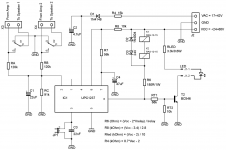
I just finished doing a protection circuit borrowing the use of an optical coupled MOSFET driver, a couple of high current trenchFETs, two dual comparators, and the usual R's and C's. It turns the FETs off if there's a DC offset greater than +/-1.5V at the speaker terminals. Needs a low current bipolar supply of +/- 9V to +/- 15V. The whole thing fits on a board 36mm by 45mm through the use of surface mount components and can mount directly to 19mm spaced binding posts. If this is what you want I can post the schematic and layout.
Yes please, thankI just finished doing a protection circuit borrowing the use of an optical coupled MOSFET driver, a couple of high current trenchFETs, two dual comparators, and the usual R's and C's. It turns the FETs off if there's a DC offset greater than +/-1.5V at the speaker terminals. Needs a low current bipolar supply of +/- 9V to +/- 15V. The whole thing fits on a board 36mm by 45mm through the use of surface mount components and can mount directly to 19mm spaced binding posts. If this is what you want I can post the schematic and layout.
Here's the schematic, the layer by layer layout and the zipped Gerbers. The amplifier connections are set up for using faston spade lugs. The control power comes in on the three pin, 2.54mm pitch, connector.
Attachments
Great, thank jhoflandHere's the schematic, the layer by layer layout and the zipped Gerbers. The amplifier connections are set up for using faston spade lugs. The control power comes in on the three pin, 2.54mm pitch, connector.
Hi, do you have DC Protector Board left ? thanks
Buy the pair and gift the spare board
We have some logistical limits on being able to sell low value items and these are a common pair.This thread isn't dead but the procedures I put in place for helpdesk staff to stay on top of answering threads doesn't seem to have worked. We'll get there. In the meantime, if you have any urgent questions please email contact@diyaudiostore.com. Thanks!
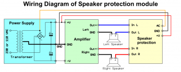
I've got to say that having this speaker protection board gives me the comfort to build solid state amplifiers. The speakers that I use and love have drivers that are out of production so I can't take the risk of damaging them. I use Hammer Dynamics Super 12s and I have a pair of Loth-X too. Both are very special to me. Tube amps are not a problem because of the output transformers. My only gripe is the lack of separation between grounds for each channel's sense circuit.
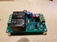
Just to throw this out there, I use a protection board I found at DiyFan.com. It's based around the uPC1237 IC. It seems to work pretty well. Attached are the schematic and hook-up files and a picture of the one I just built. I have a few extra boards if you want one. Let me know.
Attachments
I just posted to the wrong thread. Is there a way to move it? I want it to go to:
Very simple quasi complimentary MOSFET amplifier
Thanks.
Very simple quasi complimentary MOSFET amplifier
Thanks.
Hello All, i have been reading mostly around protecting speakers by loading delays, reading DC and cutting off relays etc. In case of faults like PSU failure, MOSFET/ Power Transistor etc., but what happens to Input devices, are they safe in these situations...if no then what protection to be built to ensure they are safe too...just like we have for output to speakers. I ask because I normally use my iPhone as source input to amps
Thank Jason, This Dc protector work very well.
I etched my own PCB and i tried with 12vac and 12vdc with 5 volts relay and the led stop blinking after 13s for 12vdc and 8s for 12vac
i have one 25-0-25 volt transformer for my amp that i would like to use, so i changed the 5v relays with 12v relays, when i tap one of the 0-25v to power the speaker protection board, the led do not stop blinking and do not engages the speaker relays with the connection (Amp-in connected), now if i disconnect the Amp-in the led stop blinking and engages the speaker relays after 5s.
I also tried with a separate 24vdc Power supply and the led blinked for 5s and after the same time the relays engaged (Amp-in connected).
To do simple way...
With a separate power supply the speaker protection work well and connected directly to my Amp transformer 0-25vac that do not work
Any thought...
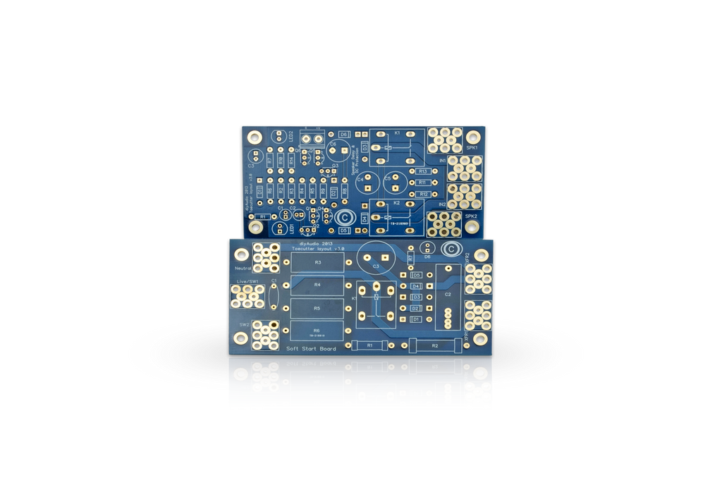
- Home
- The diyAudio Store
- Speaker Turn On Delay and DC Protector Board Set (V3)