If you look under ordering information the part number listed is one with a C after the 945 which i interpret as being the center collector version. The ones i have look identical to the ones 6L6 shows in his images.
I also have one of those cheap eBay transistor tester at home so i will unsolder one tonight and see what it says.
I also have one of those cheap eBay transistor tester at home so i will unsolder one tonight and see what it says.
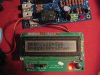
Confirmed the pinouts are ECB for those transistors, did the leg shuffle with all five of them, and rotated those four capacitors the correct way around and its working perfectly. LED1 flashes for ~six seconds on power up before the two relays turn on. DC cutoff on mine starts @ 1.95v, its not immediate as you need to apply DC for ~six seconds before it trips out.
Also for reference, i'm using an Antec AN-0124 10VA 24V Transformer, each relay coil has approx 13.4v across it.
Looks like its good to go, thanks again for the help Jojo, much appreciated
Also for reference, i'm using an Antec AN-0124 10VA 24V Transformer, each relay coil has approx 13.4v across it.
Looks like its good to go, thanks again for the help Jojo, much appreciated
Attachments
Still a doubt: the main transformer I have for amplifier board is a 2x24vac rated. But measure on secondary gives 25Vac actually. Is it too much to power the board with 2 12dc relays?
The problem is I don't have too much space in the case for another transformer...
Thanks,
Saverio
The problem is I don't have too much space in the case for another transformer...
Thanks,
Saverio
Jojo, any suggestions on the best way to manually trigger the DC potection? I want to add a mute button to the amp and figured this board would be an elegant way of doing it.
@Saverior, i would say 25v is perfectly fine, i didn't measure my 24v transformer but i would be willing to bet its output is higher than 24-25v. The Antec transformer is only 2.25" in diameter, falls into the cute category.
Cheers,
Mark
@Saverior, i would say 25v is perfectly fine, i didn't measure my 24v transformer but i would be willing to bet its output is higher than 24-25v. The Antec transformer is only 2.25" in diameter, falls into the cute category.
Cheers,
Mark
Hi,
After having built the Aleph J, one thing that's frightening is the fact that I get a lot of noise after turning off the amp. I have very high efficiency speakers so the noise gets REALLY loud.
Does this board also shut down the speaker outputs at turn-off?
Second question: my transformer is a 2x18V. I have read through this thread to see if it has come up but maybe I missed it... would I need a separate 12V transformer for this build?
Thanks, Vranc
The protect board runs on 24v so you can either connect to one half your main power supply, or use a dedicated 24v transformer.
I used a dedicated 24v transformer in my build and i can confirm on power down the relays disconnect the speakers before the main power supply discharges so i get zero noise or thumbs on startup or shutdown.
I used a dedicated 24v transformer in my build and i can confirm on power down the relays disconnect the speakers before the main power supply discharges so i get zero noise or thumbs on startup or shutdown.

Jojo, any suggestions on the best way to manually trigger the DC potection? I want to add a mute button to the amp and figured this board would be an elegant way of doing it.
@Saverior, i would say 25v is perfectly fine, i didn't measure my 24v transformer but i would be willing to bet its output is higher than 24-25v. The Antec transformer is only 2.25" in diameter, falls into the cute category.
Cheers,
Mark
Sorry for the very late reply. Instead of triggering the DC protection, you can add a pull down resistor (4.7K should be ok) at the base of Q4 to ground via a toggle switch.
Cheers
Regarding the power supply (UL1 and UL2) for the Speaker Protection Board V3:
I ordered the Antek 0124, but it does not seem to have a center tap, so if I ground one of the transformer output leads as per the schematic, there could be problems as current would short to ground.
How is the Antek 0124 hooked up on these boards? Are the two output coils completely independent (resistance measures indicates this), or is there a way to tie two leads together to make a center tap? The schematic is vague on this.
Thanks.
P.S. I cannot find a build guide for this board, only for the Soft-Start.
I figured out how to get a center tap out of the Antec transformer, but it is probably not necessary anyway.
The + and Gnd symbols on the board (and the schematic) for the supply connection is what confused me. I was ready to make a DC to supply, but reading the threads here indicated that a transformer could be hooked up directly , as there is on-board rectification. The usual squiggly line for AC would make more sense, or better yet, some explanation in a build guide.
By the way, thanks for providing these boards. They are very high quality, especially at the price.
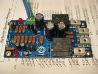
I didn't find it obvious either. Center tap is not required so i paralleled the two secondary windings of the Antek, you will also need to run a wire from the ground side of the PCB otherwise the DC detect function will not work. It detects + DC in relation to ground.
You can just about make out the wiring in the pic below..
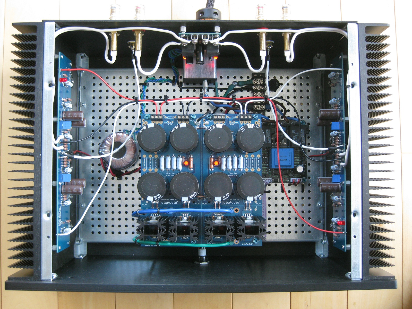
You can just about make out the wiring in the pic below..
Most Power Amplifiers use a dual polarity supply.
You can't get dual polarity from a dual secondary transformer if you
You must use either a dual secondary into dual rectifiers and then series connect the two smoothed outputs
or
use a centre tapped where the secondaries are already series connected and use one bridge rectifier to feed the series connected smoothing capacitors.
You can't get dual polarity from a dual secondary transformer if you
so i paralleled the two secondary windings of the Antek
You must use either a dual secondary into dual rectifiers and then series connect the two smoothed outputs
or
use a centre tapped where the secondaries are already series connected and use one bridge rectifier to feed the series connected smoothing capacitors.
Thanks for the advice, mcandmar. I ended up paralleling the transformer outputs and grounding one side of them from the board to the star ground.
The board seems to work fine (relays close after a few seconds after power on an off, and LED1 blinks quickly until the relays close.)
I plan on some more testing before I hook the speaker leads to it. (tthe amp itself is not in the case yet).
In earlier posts, there were some questions about transistor substitutions and pin-order. I used the Fairchild KSC945YTA for Q1, 2,3, 5, and 6, and the EBC leads matched the boards. For Q4, I used a Rectron MPSA06 and its leads matched too.
Hi Guys,
When I ordered the board, I did not buy a dedicated small 12v transformer for the speaker protection board and my F6 is finished and the speaker protection is the last part I am working on to finish the amp. I am wondering if it is possible to tap into 18 v from one side of my 2x 18 v power transformer or 24 v DC from one side of the power supply and use a L7812 voltage regulator to get 12 volts to use to power the speaker protection board.
I already have built the board with 12 volt relays.
Does the L7812 voltage regulator work with AC to make 12 v ac or will the board work with DC instead of 12v AC?
I realize this is quite a beginner question but I have found several schematics to add a few capacitors with L7812 to get 12 volt supply, and I have several l7812s on hand.
I assume running this L7812 will just give me a small drain on one power supply channel, or will this be problematic?
Ideas or suggestions appreciated. Thanks, John
- Home
- The diyAudio Store
- Speaker Turn On Delay and DC Protector Board Set (V3)