I ordered the transistors direct from the BOM, which still does not have a suitable transistor spec'd for the 945 with the right pinout. ( 2N2222 has same pinout )
It may be possible that I broke some vias/traces removing the C versions, but I don't know. At least one emitter pad is gone for sure, it came up trying to clear the hole. I got all the BC549 in the right way around, but it still does not work.
Any voltages I could test?
It may be possible that I broke some vias/traces removing the C versions, but I don't know. At least one emitter pad is gone for sure, it came up trying to clear the hole. I got all the BC549 in the right way around, but it still does not work.
Any voltages I could test?
Might want to check your work, one by one if you have time. This circuit works even with hand me down or salvaged transistors.
Be very sure of the pin orientations of your transistors, there's only a handful of parts here so it is the transistors that has the most error factor points.
Sorry no voltage points were conducted.
Be very sure of the pin orientations of your transistors, there's only a handful of parts here so it is the transistors that has the most error factor points.
Sorry no voltage points were conducted.
Q4 looks ok, thanks. Since I built up two at once, i can compare voltages at certain points. I suppose that would be best done around the transistors.
If I am not mistaken, MPSA06 could also be used throughout and shares the same EBC pinout as the 945 and 2N2222.
Can rail voltages of the amp affect transistor selection?
If I am not mistaken, MPSA06 could also be used throughout and shares the same EBC pinout as the 945 and 2N2222.
Can rail voltages of the amp affect transistor selection?
Found it... it was a pesky little solder bridge, made from solder the sucker left behind. Both sets of boards are running with 2N2222 in place of the K945. They have the correct pinout as well.
An interesting thing happens in this circuit. I am building this for an F5T, and using one board per channel, in the event I want to go to monoblocks.
I have a two stage slow charge circuit. First, a 1 minute delay before starting the fill the cap bank using NTC thermistors, then another 1 minute delay before bypassing the NTCs.
On power up, the speaker protection blinks for a while, and then engages the speaker relays. A bit later, the slow charge relay energizes to enable the slow charge of the cap bank via NTC. Nothing changes at the speaker relay. This charges the 88,000 uF per channel cap bank to around 46 VDC. Then the NTC is bypassed, at which point the cap bank settles at it's final rail voltage of about +/- 48 VDC.
When the NTC is bypassed, the speaker protector opens the relays and the red LED starts to blink again. In a few seconds, it closes the relays and the LED continues to work.
The speaker protector circuit is being powered by a 12 VA 12 VAC transformer via full wave rectifier and 7812 regulator. There is a slight drop of voltage when the NTC's engage, and no noticeable drop when they are bypassed.
THERE IS NO AMP CIRCUIT INSTALLED YET, just power supply and speaker protection.
The fuse is a 8A fast blow. Mains are around 122 VAC.
I don't mind it dropping out. I like it. But I don't know why it does that.
Hi all,
I built this board and powered it with its own 24v transformer and it seems to power up ok but i have two issues/questions.
-On power up both LED's light and both relays click on, and i have continuity between IN1->SPK1 and IN2->SPK2 so it seems to be powering up ok.
-I cant get the DC protect function to work, nor do i understand how its supposed to work. I tried applying a DC voltage to the IN1 and IN2 connections and nothing happened, then it occurred to me that my bench power supply isn't ground referenced, and neither is the protect board so how can it detect DC?
-Secondly both relays engage immediately upon power up, isn't there supposed to be a delay?
Thanks,
Mark
Hi,
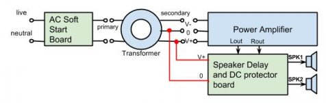
I'am not sure if the attached schema is ok. Hope it is clear. If it works I'm going to build both boards (SoftStart & Speaker delay and DC protection)
Hope someone can tell me... (total newbie....)
Thanks,
Saverio
That is how it's done. Good luck on your build.
Hi all,
I built this board and powered it with its own 24v transformer and it seems to power up ok but i have two issues/questions.
-On power up both LED's light and both relays click on, and i have continuity between IN1->SPK1 and IN2->SPK2 so it seems to be powering up ok.
-I cant get the DC protect function to work, nor do i understand how its supposed to work. I tried applying a DC voltage to the IN1 and IN2 connections and nothing happened, then it occurred to me that my bench power supply isn't ground referenced, and neither is the protect board so how can it detect DC?
-Secondly both relays engage immediately upon power up, isn't there supposed to be a delay?
Thanks,
Mark
Kindly check all your transistors. Check their values and especially their pinouts. There should be a 4-8 second delay which means the LED will blink for about 4-8 seconds before it goes steady ON.
At this stage there should be continuity between in1 and spkr1, same as the other relay.
If using a separate psu, it is of course mandatory to ground reference the separate psu to the psu of the amp for the DC protect to work.
Thanks Jojo, the transistors i ordered were exactly the same part number as the BOM, x1 583-MPSA06, x5 512-KSC945CGBU. I doubled checked the datasheets and confirmed they are all EBC layout the same as marked on the board.
Noted on the DC grounding, how much DC is allowed before the relays trip out? are we talking millivolts or volts.
Noted on the DC grounding, how much DC is allowed before the relays trip out? are we talking millivolts or volts.

Good job i did read all that again, when i glanced at the datasheet it shows the transistors as being EBC, but if you read the fine print and double check the part number from the BOM they are the ECB version so looks like i have to do the leg shuffle on all five of them too.
Would it be too much to ask for somebody to update the BOM, the error was discovered back in February
Would it be too much to ask for somebody to update the BOM, the error was discovered back in February
- Home
- The diyAudio Store
- Speaker Turn On Delay and DC Protector Board Set (V3)