Thank you Andrew for your response.
My understanding is that it would be possible to run both the soft-start board and turn-on delay+DC protector board combo with a small additional transformer.
Would a 30VA toroidal transformer with 2 x 12VAC output at 1.25 amps be enough?
My understanding is that it would be possible to run both the soft-start board and turn-on delay+DC protector board combo with a small additional transformer.
Would a 30VA toroidal transformer with 2 x 12VAC output at 1.25 amps be enough?
that 1.25Aac converts to just over 630mAdc after the rectifier and capacitor input filter.
If you have a continuous DC load, then I suggest you only use 50% of that maximum continuous DC, i.e. limit your consumption to <=330mAdc continuous.
That is plenty for soft start and DC protect & delay.
4 relays @ 40mA = 160mAdc two circuits @ 20mA = 40mAdc. You are upto a max continuous of <200mAdc and more likely <100mAdc.
I have used 6VA for each of those.
Last edited:
Thanks again Andrew for your kind explanation.
Have a couple of questions on the relays:
- Since the relays of the DC protect + delay PCB are in series, I should use 5V relays for that board with a 12VAC transformer? (as pointed out by Prasi a few posts back)
- For the soft start board, use the 24V relay irrespective of power supply voltage?
Have a couple of questions on the relays:
- Since the relays of the DC protect + delay PCB are in series, I should use 5V relays for that board with a 12VAC transformer? (as pointed out by Prasi a few posts back)
- For the soft start board, use the 24V relay irrespective of power supply voltage?
Just checked Andrew - the 5V relay listed below has coil current of 80mA, and the 24V relay has coil current of 15mA:
http://www.mouser.com/ProductDetail/Omron-Electronics/G5Q-14-DC5/
http://www.mouser.com/ProductDetail/Panasonic-Industrial-Devices/JS1-24V-F/
The power consumption however is rated at 400mW for the 5V relay and 360mW for the 24V relay, which are similar/closer.
Good learning for me.")
http://www.mouser.com/ProductDetail/Omron-Electronics/G5Q-14-DC5/
http://www.mouser.com/ProductDetail/Panasonic-Industrial-Devices/JS1-24V-F/
The power consumption however is rated at 400mW for the 5V relay and 360mW for the 24V relay, which are similar/closer.
Good learning for me.
400mW is very high. Is the current rating of the contacts very high?
Sorry - I am unable to understand the question above, can you please elaborate a bit?
If you use 80mA relays, then your transformer rating may have to be slightly higher.
The 5V regulator (if fitted) is going to be pretty hot.
Can you please share a SKU of 5V relay with less mA rating that would work in this application? Or, with a 2 x 12V transformer, would 12V relays work?
low power relays typically draw 120mW to 140mW. They require a high compliance contact that pulls in towards the solenoid without a big magnetic force.
High power relays tend to be built to develop a lot of magnetic force to be able to pull in a low compliance contact that is built to pass very high current.
That's why I asked
High power relays tend to be built to develop a lot of magnetic force to be able to pull in a low compliance contact that is built to pass very high current.
That's why I asked
Is the current rating of the contacts very high?
The soft start contacts see nothing at first start up. They remain open.
They close after the delay has expired and the transformer is already being partially powered via the current limiting resistor. Very little contact damage/erosion happens during contacts closing.
Most damage happens when contacts open and break the current flowing to an inductaive load.
At power off the relay contacts remain closed until the back emf and any possible ringing has collasped. There is no turn off duty for the soft start relay. (quite different from the speaker protection relay).
That means the contacts in the soft start relay can be low current. Typically you will find 250Vac 2Aac contacts on small low power relays and I have not found any failures using that rating even though I have been using them in various projects for over 40years.
Some (only a very few) have been on 1000VA 230VA toroid transformers used on upto 250Vac.
Last edited:
Hello here
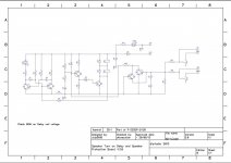
Some time ago, i made myself this DC-protector board.
I did raise C3 from 47uF to 100uF for delaytime of approx. 8-10 sec.
It is stuffed with relay's for 24vdc PSU. (2x12vdc omron's as per BOM)
Nothing else changed, created from scratch from attached schm.
Well, right now i am coocking on a Aleph J - mini, with psu rail's at 19,2vdc, and i attached the protection board to the Aleps PSU.
Eventhrough the rails are lower, everything seems to work. I meassured at the relay's coil and the relay's engage around 7vdc; when they are engaged the voltage across them is around 9,5vdc (~Half my 19vdc psu i think)
So far so good
Last evening i tried to power it up, with everything connected (source, AlephJ and DC-protection boards).
As can be seen and heard on the youtube video the board engages the relays after ~8 sec. and speakers are then connected (You can hear the click from relay here on video)
At first in video, the sound which can be heard is my switch for 230vac mains switch, so just ignore this sound.
When i cut the mains, you can hear relay and a little "nasty" sound on speakers?
Anyone know, why this happens?
For years i have used a Velleman K4700 protection board, and this board does not give this "nasty" click in speakers?
Thanks in advance.
https://www.youtube.com/watch?v=oOhNijAlyFk
Attachments
hi,
you should use a AC loss detection functionality for nasty sounds after switch off. this is available in UPC1237. my opinion only!
reg
Prasi
Thanks...
I just purchased this one below, so to try that out later.
Meantime i just connect amp. without any protection board (makes no noise)
Jesper.
UPC1237 Dual Channel Speaker Protection Circuit Board Boot Mute Delay DC 12-24V | eBay
Options for DC Protection board relays
Hello All,
As of 4:45 est neither of the relays in the BOM are available. The 12v ones are indeed listed as obsolete, and now the 5v ones are no longer available and slated for obsolescence. Has anyone found comparable 12 or 5 volt relays that will fit the PCB?
Thanks!
Hello All,
As of 4:45 est neither of the relays in the BOM are available. The 12v ones are indeed listed as obsolete, and now the 5v ones are no longer available and slated for obsolescence. Has anyone found comparable 12 or 5 volt relays that will fit the PCB?
Thanks!
Power for speaker protector
Hey everybody. I realize my question has probably been answered somewhere else but I can't seem to find the answer I need. I just finished my F5 amp and I want to add the v3 speaker protect board. I have 2 12v relays and an Antek 10VA 24V transformer. I was wondering though if I could just use one of the V+ connections from the F5's psu which outputs 24-25vdc? I've had some transformer hum problems with my F5 and would like to avoid adding another transformer, even a small one. Is there a reason using the DC from psu would be a bad idea? Would it have an effect on the F5 boards, biases etc. I'm assuming that if I went that route I would connect PSU V+ to the speaker protect pcb's V+ and the speaker protect G to the PSU ground, correct? Also, do I just omit D3,D4,D5and D6? Or do I need to jumper those? Anything else I would need to omit or jumper? If you guys think it's better to use a separate transformer where should I tap into the mains AC, on the terminal block where my F5 transformer connects to mains AC through CL 60 thermistors or should I tap in directly at the power entry module? Also, my transformer has 2 outputs with blue and green wires. Would I just use one of those outputs, one blue and one green, and just seal off the other two wires? Thanks for any advice.
Hey everybody. I realize my question has probably been answered somewhere else but I can't seem to find the answer I need. I just finished my F5 amp and I want to add the v3 speaker protect board. I have 2 12v relays and an Antek 10VA 24V transformer. I was wondering though if I could just use one of the V+ connections from the F5's psu which outputs 24-25vdc? I've had some transformer hum problems with my F5 and would like to avoid adding another transformer, even a small one. Is there a reason using the DC from psu would be a bad idea? Would it have an effect on the F5 boards, biases etc. I'm assuming that if I went that route I would connect PSU V+ to the speaker protect pcb's V+ and the speaker protect G to the PSU ground, correct? Also, do I just omit D3,D4,D5and D6? Or do I need to jumper those? Anything else I would need to omit or jumper? If you guys think it's better to use a separate transformer where should I tap into the mains AC, on the terminal block where my F5 transformer connects to mains AC through CL 60 thermistors or should I tap in directly at the power entry module? Also, my transformer has 2 outputs with blue and green wires. Would I just use one of those outputs, one blue and one green, and just seal off the other two wires? Thanks for any advice.
hi, see my post no. 236 for 5v subs. the link for 12v http://www.mouser.in/ProductDetail/...GAEpiMZZMtSzCF3XBhmW97xBhRVUmus6Z%2bft4FTgu8=Hello All,
As of 4:45 est neither of the relays in the BOM are available. The 12v ones are indeed listed as obsolete, and now the 5v ones are no longer available and slated for obsolescence. Has anyone found comparable 12 or 5 volt relays that will fit the PCB?
Thanks!
just check the footprint size on pcb (length for panasonic is 22mm and for omron is 19.8mm). if this dimension fits on pcb, you are good to go.
reg
Prasi
Thanks Prasi, so I can just leave all the diodes even if I'm using DC? That would be a lot easier. I thought I might have to change/omit some components since the BOM specifies 12 or 24VAC.hi dbis,
d3 d4 are for relay back emf. there is no harm in keeping all diodes.
my suggestion would be to first try with amp psu +24v/25v supply and use 12v relays. check to see delay is proper and there is no shutdown noise.
reg
Prasi
yes, again.... i take that leaving all diodes means keeping all in....Thanks Prasi, so I can just leave all the diodes even if I'm using DC? .
sorry my English is poor and recently i was 'insulted' for my poor English on this technical forum...what an irony
Sometimes I feel like insulting native english speakers for their poor use of english. Thay haveno excuses.
I can always forgive non native speakers. They at least try to talk/type our silly language.
I was hopeless at foreign languages at school, so untimately I became a teacher.
I can always forgive non native speakers. They at least try to talk/type our silly language.
I was hopeless at foreign languages at school, so untimately I became a teacher.
- Home
- The diyAudio Store
- Speaker Turn On Delay and DC Protector Board Set (V3)