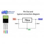
The circuit with 7812 is incredibly simple, just a small cap (value not very critical) on each side of the regulator. If you get one in TO-220FP (the plastic insulated version) you can just attach to the chassis floor for heatsinking. The caps and wires can be attached directly to the pins.
Attachments
Last edited:
Adjustments for F4?
Hello")
Uhm, so for the F4 which becomes true, what adjustments should I make concerning the bleeder resistor (R9, R10), and since I‘ll try making the rectifier part too, is the output snubber required? (Not sure anymore about this, whether it is not required because of the constant current draw of a class-A amp?
I‘ll try not to ask too many too basic question (except these 2 for a starters)
Thank you
All the best
d.
Hello
Uhm, so for the F4 which becomes true, what adjustments should I make concerning the bleeder resistor (R9, R10), and since I‘ll try making the rectifier part too, is the output snubber required? (Not sure anymore about this, whether it is not required because of the constant current draw of a class-A amp?
I‘ll try not to ask too many too basic question (except these 2 for a starters)
Thank you
All the best
d.
Adjustments for F4?
Hello
Uhm, so for the F4 which becomes true, what adjustments should I make concerning the bleeder resistor (R9, R10), and since I‘ll try making the rectifier part too, is the output snubber required? (Not sure anymore about this, whether it is not required because of the constant current draw of a class-A amp?
I‘ll try not to ask too many too basic question (except these 2 for a starters)
Thank you
All the best
d.
Bleeder resistor is there to discharge the capacitor bank after power-off. It’s value is not critical at all. 2.2k is a common value and works perfectly. Anything from 1.5k to 10k is again, completely fine.
Leave the output snubber open. The next PSU will not have one, it’s worthless.
Leave the output snubber open. The next PSU will not have one, it’s worthless.
I have build a Universal Power Supply circuit board. It seems to work fine and i tested it with my M2x boards, drawing 2,6A per PSU rail. My toroid ist a bit oversized with 500VA.
My negative voltage rail seems to have unmeasurable AC voltage at the output, while my positive rail measures around 50 mV ripple voltage. Measurements are the same with load applied or without load.
I triple checked all solder connections. Does anyone have an Idea how to find the culprit?
My negative voltage rail seems to have unmeasurable AC voltage at the output, while my positive rail measures around 50 mV ripple voltage. Measurements are the same with load applied or without load.
I triple checked all solder connections. Does anyone have an Idea how to find the culprit?
I will answer my own question. First i realised that i used a wrong range setting for measuring the AC ripple voltage at the output. When i use the "mV" setting my DVM reads around 7mV ripple (not 50mV) between V+ and ground.
My DVM only measures AC voltage when i connect the red clamp to the point with higher DC potential and the black probe to the point with lower DC potential. To measure the positive rail i had to connect the red clamp to V+ and the black clamp to ground. To measure AC ripple voltage on the negative rail i had to connect the red probe to ground and the black probe to V-.
Using this method and the mV range on my DMM both positive and negative rail measures AC ripple voltage around 7mV.
I will repeat measurements next weekends using my CRO. I was too lazy to set it up in my living room workshop that must be cleaned after every DIY session.
Last edited:
Class AB amps draw varying amount of current so a CRC filter would vary the voltage available, depending on the value of the resistor. The current could vary from tens of milliAmperes to many Amperes, so the power supply voltage variation due to the voltage drop across the resistor could be quite large.
Class A amps on the other hand have only small current variation so the power supply voltage variation is quite small.
Although a C filter has much higher ripple than a CRC filter, Class AB amps are push-pull and they have high Power Supply Rejection Ratio (PSRR), so higher ripple can be tolerated compared to a single ended amp which has low PSRR.
Howdy!
I have my boards and transformers ordered, and I'm getting ready to order components to stuff the board with. I'm very new to this and have been learning a ton as I put this all together, so I'm hoping for a quick sanity check before I put more money down.
I'm building an F5T v2 with cascodes. I'm intending to build it dual mono. To that end I've ordered two Antek AN-6224 transformers (600VA 24V 12A + 24V 12A). I've also ordered two sets of UPS v3 boards and one Soft Start board.
For the filter boards, I'm looking at 15kuF caps. The ones I've selected are Nichicon 35mm caps, snap in with 10mm lead spacing, rated to 105C and claiming decent ripple capabilities. For the caps I'd like to stuff all 7 positions on each rail with >=4W 0.47ohm resistors but I haven't selected a specific part yet.
If I'm understanding how to use PSUD2 properly, it looks like I'll get a fairly clean 32V out of each UPS rail, taking around 25s to get there. Although when I zoom in on a slice of the load voltage it does seem to still ripple 0.32V peak to peak. Not sure if that is normal/good or if I'm using the software wrong or something. Getting 32 out makes me feel like I must be doing something right.
There seem to be a lot of package choices for the diodes. Is there a preference? In researching the part number in the BOM it seemed like there weren't a ton of heatsink options for that specific package, but it's probably more flexible than I'm thinking.
I don't think I'm going to build the protection board that comes with the Soft Start board, but if it's recommended I'm open to reconsider. On a similar note I don't see anybody populating the snubber components on the UPS diode boards, are those typically omitted? Or maybe people are using them and I'm just blind? It seems like most people just populate the diodes to build the rectifier and don't put anything else in those boards, which seems fine to me.
What do you think? Looks good?
Thanks for your time!
Hi
Novice here.
I recently got mine (PSU) working, so I have some ideas.
Does the ripple eventually come from the 7 (instead of 4) 0.47r resistors? Just a thought...
Leave the output-snubber.
Install the input-snubber, make sure the values are good with your transformers (look for threads „quasimodo“ (one is about the jig, one is for the results. (Also, look for Mark Johnson‘s „soft-start“—it‘s a different beast, but you‘ll learn a lot about softstart-procedures...
Will you be building a dual mono in one case? (One softstart-board suggests so)
Happy building, you will like it and you will enjoy the community here!
d
Hi
Novice here.
I recently got mine (PSU) working, so I have some ideas.
Does the ripple eventually come from the 7 (instead of 4) 0.47r resistors? Just a thought...
Leave the output-snubber.
Install the input-snubber, make sure the values are good with your transformers (look for threads „quasimodo“ (one is about the jig, one is for the results. (Also, look for Mark Johnson‘s „soft-start“—it‘s a different beast, but you‘ll learn a lot about softstart-procedures...
Will you be building a dual mono in one case? (One softstart-board suggests so)
Happy building, you will like it and you will enjoy the community here!
d
Thanks! Yeah, that's the plan, a F5Tv2 with cascodes in dual mono in a 5U chassis.
In PSUD2 I have a CRC filter set up but I don't know how to increase the number of each component, so I have just been plugging the section totals into a single component if that makes sense. If I drop R to 4*0.47=1.88ohms I still get the same 120hz ripple. It only shows up if I only look at V(R2) which is my load voltage. If I take a 1s slice after a 120s reporting delay I'm seeing a wave that is 120hz and around 0.00024V peak to peak. Maybe that's as good as flat? Can't help but feel like I'm missing something obvious.
I'm sure this has been asked a million times but I can't find the answer. I have a cart on the DIYAudio.com store with all the stuff they sell that would let me build a F5 and a F6 except for the power supply. All I can find there for that is a PC Board and no clear instructions about whether I need 1 or 2 of those or how I would get the parts for it much less the transformer etc. etc..
Obviously, I'm a newbie to this so my preference is just to order 1 kit with everything I need for the power supply or even better to order a pre-built power supply that I can just stick in the Deluxe 4U chassis. Is there anything like either of those two options and where would I find them?
Thanks.
just been plugging the section totals into a single component if that makes sense. If I drop R to 4*0.47=1.88ohms ...
Hi VM
Sorry it seems I missed this reply for ages.
Careful with this procedure you’re describing, as those 4 0.47r resistors don‘t sum up to 1.88. they‘re parallel, not in series, and so they will actually divide, while they‘re rating (wattage) sums up. They end up being a 0.12r 12 W resistor...
Here‘s a calculator for that stuff: Blocked
As to your scope-investigation, I can‘t comment on this, I haven’t touched mine yet...
I'm sure this has been asked a million times but I can't find the answer. I have a cart on the DIYAudio.com store with all the stuff they sell that would let me build a F5 and a F6 except for the power supply. All I can find there for that is a PC Board and no clear instructions about whether I need 1 or 2 of those or how I would get the parts for it much less the transformer etc. etc..
Obviously, I'm a newbie to this so my preference is just to order 1 kit with everything I need for the power supply or even better to order a pre-built power supply that I can just stick in the Deluxe 4U chassis. Is there anything like either of those two options and where would I find them?
Thanks.
Power supply is where you need to put some effort in yourself and where DIYAudio let you solo a bit. And for good reason. Transformers are heavy and shipping charges can be astronomical depending where you are. So best economy is to source yourself. And to read the PSU Build Thread from the start. Generally you will need to get one board per transformer. And mostly one transformer and PSU board feeding both amp boards is good enough.
Last edited:
I'm sure building the power supply is completely straightforward once you do it but I'm still struggling with the fact that I can't find step by step instructions and there seems to be quite a bit of leeway as to what parts you even use.
So given my resistance to figuring that out I am curious if you could just use two auto batteries in series to provide 24VDC to power the F5 or F6 amps?
So given my resistance to figuring that out I am curious if you could just use two auto batteries in series to provide 24VDC to power the F5 or F6 amps?
- Home
- The diyAudio Store
- V3 Universal Power Supply Circuit Board