I'm worried about the thermistor epcos because it's not marked cl-60 but it's 10ohm and 5a
You should first try to source the CL-60, it's pretty much available online.
the important line in the short form spec isA suitable capacitor - WYO332MCMCF0KR Vishay / Roederstein | Mouser
AC Line Rated Class X1/Y2 Capacitors
You also need the correct joules to ensure you don't blow it up.I'm worried about the thermistor epcos because it's not marked cl-60 but it's 10ohm and 5a
Should I tie the grounds of both the positive and negative rail together for my F5? Looks like Nelson Pass did that on his power supply board: 6moons audio reviews: FirstWatt F5
Last edited:
star ground question: Is the concept to bring every ground from every board (even the single ended RCA input too?) to a single slab of copper?
I have some 1/8" x 3/8" bar stock that would do if this is the case...
P.S. I know the chassis gets a single ground at or near the IEC connector.
I have some 1/8" x 3/8" bar stock that would do if this is the case...
P.S. I know the chassis gets a single ground at or near the IEC connector.
star ground question: Is the concept to bring every ground from every board (even the single ended RCA input too?) to a single slab of copper?
I have some 1/8" x 3/8" bar stock that would do if this is the case...
P.S. I know the chassis gets a single ground at or near the IEC connector.
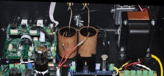
Here's a picture of my DAC employing a single point ground using a #8 bolt with soldered ring tabs. Every PCB (or item) that requires a GND is returned to this point. Ideally, all grounds should be the same length as the purists will tell you. Have used this method in every piece of equipment I have made and I can tell you it's the best way to implement it. I cannot emphasize the importance of ensuring AC Line and Neutral connections are kept consistent and correct from transformers in each piece of equipment and between components to ensure the quality and safety of this approach.
BTW - the term "star ground" is typically used when describing PCB ground methods. When wiring a chassis, the ground point can be at any location as long as the "star points" (the wires) are reasonably close in length.
Attachments
Last edited:
Thanks! That's a fine looking DAC you have made there!
I'd forgotten the restriction of all the leads being of the same length, thanks!
I was told on my first build of a vacuum tube amp that the components are all brought to the same point or at least same copper (thick) wire and the chassis got its own single ground. I used this idea and it worked fine, I just sort of forgot about it when doing all the research around this Aleph J build.
SS must be different than tube work. SS sure has its advantages")
Cheers!
I'd forgotten the restriction of all the leads being of the same length, thanks!
I was told on my first build of a vacuum tube amp that the components are all brought to the same point or at least same copper (thick) wire and the chassis got its own single ground. I used this idea and it worked fine, I just sort of forgot about it when doing all the research around this Aleph J build.
SS must be different than tube work. SS sure has its advantages
Cheers!
star ground question: Is the concept to bring every ground from every board (even the single ended RCA input too?) to a single slab of copper?
I have some 1/8" x 3/8" bar stock that would do if this is the case...
P.S. I know the chassis gets a single ground at or near the IEC connector.
I'd say Roger's photo of his DAC is a very good example of employing single point star ground. There are a lot of variations though but the whole concept is pretty much the same.
Cheers
I'd say Roger's photo of his DAC is a very good example of employing single point star ground. There are a lot of variations though but the whole concept is pretty much the same.
Cheers
Thanks! That's a fine looking DAC you have made there!
I'd forgotten the restriction of all the leads being of the same length, thanks!
I was told on my first build of a vacuum tube amp that the components are all brought to the same point or at least same copper (thick) wire and the chassis got its own single ground. I used this idea and it worked fine, I just sort of forgot about it when doing all the research around this Aleph J build.
SS must be different than tube work. SS sure has its advantages
Cheers!
Thanks for the kind words.
As with solid state, tube circuits can also have ground loops that will trigger oscillations. In fact, tube circuits can be somewhat more prone due to the use of interstage coupling capacitors and any global feedback. Always good to play it safe and provide paths for return currents to a common node no matter what your amp flavor.
I'm thinking about jumping into the Pass domain and will probably build one of the amplifiers. However, I will end up designing my PCB's as I have preferences in components, especially caps - but will of course stick with the
known and recommended FETS.
Hope to exchange more notes in future. Thanks guys...
I also build tube amps and preamps, and I totally agree that grounding can be a serious issue. It could spell a hum-free build or worse, buzzing like crazy.
Does anyone have a figure for inrush current on an Aleph J? Can I use a CL-80 instead of a CL-60 (3A instead of 5A)?
I would strongly suggest that you keep using what is recommended. The numbers are there for a reason, sometimes for as simple as reliable operation.
Does anyone have a figure for inrush current on an Aleph J? Can I use a CL-80 instead of a CL-60 (3A instead of 5A)?
If the author of the circuit indicated a 5A device, perhaps it's safest to stick with it. If you are familiar with the circuit's consumption, you can always refer to the datasheet from GE. It also includes good theory on calculating device requirements based on steady state current and other criteria. Take special note of the section "Energy surge at turn on"
http://www.ge-mcs.com/download/temperature/920-325D-LR.pdf
If you are using a toroid transformer - between that and a couple of 20kuf plus filter caps, expect seriously high inrush peaks, probably in the order of 80A to 100A, albeit for only a few tens of milliseconds.
If I build the supply, I would design in a relay to shunt the inrush to a load resistor for a couple hundred milliseconds to alleviate this.
- Home
- The diyAudio Store
- V3 Universal Power Supply Circuit Board