The jumpers, connection points and bleeder resistors look correct.
Did you test the LEDs to ensure correct orientation? If they don't light up when they see voltage, may need to physically rotate them 180 degrees.
Also, are you planning on installing filter resistors (R1-R8)?
Can you post pics of the backside? Always good to see how the solder flowed on both sides, especially for your screw terminals. Might want to go back and touch up a few pads so you have complete solder coverage. Not always necessary but in high current circuits want to make sure plenty of surface area is available for the electrons to flow.
I have growing concerns that the voltage in this project are over 48 Vdc - which can be lethal .
The caps on this power supply will be charged up to a lethal 65 Vdc .
Do you have another transformer something in the order of 100 VA with 12 Vac dual secondaries ?
Use this as a test transformer .
I strongly advise against building and testing this power supply board with your Avel Y23 transformer
as this will create lethal voltages .
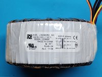
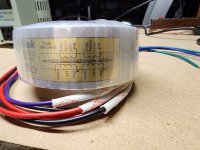
So your Avel transformer is in the Y23 series . Is the model number Y236857 ? Is this correct ?
https://www.parts-express.com/Avel-Y236857-625VA-45V45V-Toroidal-Transformer-122-695?quantity=1
If so , it is a dual secondary transformer .
For use in North America , on PRIMARY side the BLU/VIO get connected to each other
and the GRY / BROWN are to be connected to each other.
On the SECONDARY side , the BLK and and RED are 1 secondary , 45 Vac - 0
The ORG and YEL are the other secondary , 45 Vac - 0 .
.
The caps on this power supply will be charged up to a lethal 65 Vdc .
Do you have another transformer something in the order of 100 VA with 12 Vac dual secondaries ?
Use this as a test transformer .
I strongly advise against building and testing this power supply board with your Avel Y23 transformer
as this will create lethal voltages .
So your Avel transformer is in the Y23 series . Is the model number Y236857 ? Is this correct ?
https://www.parts-express.com/Avel-Y236857-625VA-45V45V-Toroidal-Transformer-122-695?quantity=1
If so , it is a dual secondary transformer .
For use in North America , on PRIMARY side the BLU/VIO get connected to each other
and the GRY / BROWN are to be connected to each other.
On the SECONDARY side , the BLK and and RED are 1 secondary , 45 Vac - 0
The ORG and YEL are the other secondary , 45 Vac - 0 .
.
Hi Uunderhill,
I totally respect your concerns. I had planned on using a variac and dim bulb tester to limit voltage and current.
I originally chose this project because I had the toroid from a project I abandoned years ago and it meshed well with this amp.
However...the amp will have more power than practical for my needs. I have now invested significant time and money on enclosures and parts. At this point buying another transformer with less voltage isn't necessarily a problem. I can ask around on the Honey Badger build thread, but I seem to recall that this amplifier can operate well down to around 35-40 volts. Thanks for your time and concern. As always, I appreciate your time and expertise. Dave M.
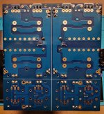
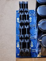
The backside of my PSU board. Not my best work necessarily. It took awhile for me to realize that I needed to crank up the heat on my soldering iron. The areas around the LED's need to be cleaned up. One Euro connector needs attention also.
When all done, I will clean the backside with flux remover.
When all done, I will clean the backside with flux remover.
Attachments
Yes , Dave , the good news is that if the Avel transformer has the model number Y236857
then it does match with the V3 board and the Honey Badger Amp .
Populating this board is quite straight forward , but the consequences of making a mistake
can be catastrophic - especially with lethal voltages .
So as someone starting off and learning , I would say you have 2 options .
1 ) Hold off on this project for now , and build a matching buffer or preamp , that has +/- 25 Vdc voltage rails .
This will give you more experience .
2 ) Find a 100 VA transformer with 9 Vac or 12 Vac secondaries . Use this as a test transformer for the V3 board .
.
Now can you help me with the cast iron plumbing in our 1958 house ?
It took awhile for me to realize that I needed to crank up the heat on my soldering iron.
Yes it looks like more heat was required so the solder could flow easier .
Do not breath in the fumes , regardless of what solder you are using .
Nothing but air goes in the lungs . As I say , even bakers in the Victorian Era suffered from respiratory issues
by the time they were 50 years old , from all the flour they inhaled
.
UncleMud if you find the diyaudio universal ps boards to be a little confusing a member R. Thatcher has some very nice ps boards available on Etsy he is the real deal and I have a few of them myself they are less confusing and he is very knowledgeable don’t be afraid to contact him

Hey fellow forum members,
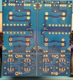
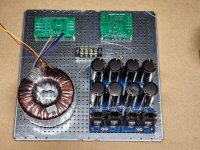
Offering up a couple updates on my Honey Badger PSU. PSU board is now complete for better or worse. My options for caps narrowed with each spec I added to the filters. I did the best I could.
Avel Lindberg transformer is indeed model number Y236857 so we're good there. I did order a 100VA 12v transformer to use for testing my PSU. Should be here in a couple of days. Unless I can make use of that transformer in a future build, I may put it in a small enclosure along with appropriate terminals for a dedicated 12v power supply to use for testing.
Also, beginning to contemplate possible layout scenarios. Using the 4U Deluxe chassis from the audio store so amp boards will be mounted directly on the heatsinks.
Lastly, finally figured out a mental strategy for understanding the flow and function of the PSU board. I ignore the numerous connection pads and look at the outline of the actual circuit. It's actually fairly straightforward. I'm learning as I go.
Cheers, Dave M.
Attachments
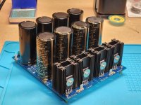
not to throw a monkey wrench in the works. By chance, did you use some double sided tape or dabs of hot glue to secure the filter caps to the board?
Asking as given the size, especially the length, caps might need a little more mechanical clamping to make sure they stay attached to the board over the lifetime of the amp.
Asking as given the size, especially the length, caps might need a little more mechanical clamping to make sure they stay attached to the board over the lifetime of the amp.
Also, beginning to contemplate possible layout scenarios. Using the 4U Deluxe chassis
Strongly Advise
1 ) Building and testing circuitry 1 stage at a time ... in the smallest steps possible .
So it would be best to solder on the diode bridge , temporarily solder on a 10 K ... 1W resistor as a load , measure the voltage
before soldering on the electrolytic caps .
Even a 100 uF charged up to 24 Vdc will give off one heck of a good zap .
Using the prayer technique , building the whole thing and praying that it works , is not a good idea .
You've soldered in R9 and R10 , so the caps can discharge - this is very important .
At this point , since the large electrolytic caps have already been soldered in , best to keep them soldered in .
As discussed previously , the Pi resistors should be soldered on the board .
For testing , connect a 10K 1 W resistor between + V and Gnd and another 10 K between the - V and Gnd .
Use a low voltage transformer as discussed .
2 ) Investigate what other people have done first .
Actually , in high tech , the first stage in design is to take your competitor's products apart .
So in this case , look carefully at the way Nelson Pass has laid out the F5 .
http://www.6moons.com/audioreviews/firstwatt9/f5.html
The transformer is near the face plate , and the power supply board is near the back .
This will allow the high current wiring to be short and have a low Independence .
Look even closer , you'll see in the F5 , the Ground wire from the RCA , the analog ground from the power supply ,
the ground wire from the speaker terminal and the amp ground are all connected in the same node ( location ) .
So everything is referenced to the same " 0 " Vdc .
Scroll down and look at the way 6L6 has laid out the components in the case .
https://www.diyaudio.com/community/threads/f5turbo-illustrated-build-guide.254056/
Once again , the transformer is near the face plate , and the power supply board is at the back .
The speaker binding posts are at the bottom and are horizontal .
I would have put the power switch on the left side of the front , but that's my style .
Both the hot and neutral need to be switched .
.
Thanks @Uunderhill,
I'll study these suggestions and related examples. I believe I already have a couple of 10k 1 watt resistors. If not, I will order some. Received word that the 100VA 12v transformer has shipped. I'll slow down and get the PSU right before moving on. Thanks for the guidance on this portion of my build.
I'll study these suggestions and related examples. I believe I already have a couple of 10k 1 watt resistors. If not, I will order some. Received word that the 100VA 12v transformer has shipped. I'll slow down and get the PSU right before moving on. Thanks for the guidance on this portion of my build.
Hello forum members,
Update on my build...
I'm a bit unsure how to proceed on my Honey Badger PSU regarding Pi resistors. On the BOM they are listed as "optional." It seems many builders have not used them. The thought seems to be that the power supply rejection ratio is sufficient without them. Is there a critical issue with either choice?
I have the Schurter 4304-6090 inlet module with 2 pole switch and fuses for power. Just to be sure, I checked the line and neutral leads with a continuity tester and both switched to an open circuit as desired.
I will have to order some resistors as suggested for load while testing the PSU when the time comes.
I studied the examples of ideal transformer and PSU placement as Uunderhill suggested. This was very helpful. I knew that proper layout and careful wire dressing were important, but it helped to see what that actually looked like. Thanks everyone. Dave M.
IMO its critical to have both , supply rails with a low noise floor & low ripple , as well as an amp design that has a good PSRR .
The power supply is 1/2 the sound . This is why when you look inside great power amps , great lengths have gone into the power supply .
Look inside Nelson Pass's XA25 power amp .
https://6moons.com/audioreview_articles/pass-labs-xa25/2/
Adding the Pi resistors will lower the ripple .
Suggest using a spacer when soldering the Pi resistors in , so there is an air gap between them and the board .
Because you've added screw termination blocks to the V3 board , test resistors can be connected to these .
The value of the test resistor is not critical , you could just twist the leads of two 22K 's together .
VERY IMPORTANTLY
1 ) as discussed , use a low voltage transformer
2 ) After measuring the voltage , those massive caps will take time to discharge .
Bit rusty at this , but Tau is one time constant , Tau = R x C .
The caps will discharge logrithmically based on the number e - they don't discharge linearity .
It takes 5 Tau for the caps to discharge to 99 %.
So the discharge resistor on your board is 22 K , and if you use a 10 K load test resistor .
Suppose each cap on you board is 10,000uF , this means
Tau = 22K // 10 K x ( 4 x 10,000uF ) = 275 s
5 x Tau = 1375 seconds = 23 minutes .
So after measuring the voltages on this power supply board , let it sit for 23 minutes with power off
to allow the caps to discharge .
.
Last edited:
Thanks for the feedback on Pi resistors. I will probably add them then.
The time needed to discharge caps is something I'll be careful about. I'm going to bookmark that equation.
Still waiting for the 12v transformer so I won't be testing anytime soon.
Thanks for being so generous with your time and knowledge.
The time needed to discharge caps is something I'll be careful about. I'm going to bookmark that equation.
Still waiting for the 12v transformer so I won't be testing anytime soon.
Thanks for being so generous with your time and knowledge.
Hello Forum Members,
Looking for some guidance on my attempt to test the V3 PSU that I plan to use on my Honey Badger build.
As suggested, I purchased a 100VA 12v transformer to use for testing. I'm also using a variac so that I can bring voltage up slowly. I don't know if it's necessary, but I do have a dim-bulb tester that I could insert if recommended.
I wired the primary wires of the transformer to the leads of a 3 way power plug and tightly wrapped them with electrical tape. (I plan to take them apart after this task and build a small enclosure for the testing power supply). I soldered the two red primary transformer leads together with the black line wire from the plug. The two black primary transformer leads were soldered together with the white neutral wire of the power plug.
The transformer has dual 12v outputs. Two green and two blue.
Am I correct that a volt meter connected to one green and one blue lead should net me 12volts AC?
I would love suggestions on whether the greens or the blues go to the A terminals and which to the B terminals.
Thank you for your time. Dave M.
Attachments
- Home
- The diyAudio Store
- V3 Universal Power Supply Circuit Board