This thread is for discussions about the F-5T clone boards. For more information on this product, please see the product page below.
Threads on diyAudio that relate to this product (If we have missed one, please post it in this thread and we will add it to the list):
BILL OF MATERIALS
The current set of boards available from the store comes in a set of 6 boards with the SKU of P-F5T-6V30 (that SKU decodes to "PCB, F5T, 6 pieces of revision 3 of the boards"). Please note that the fact it's revision 3 of the boards has nothing to do with whether you are making a V1, V2, V3 or V99 F5T and just means it's the third revision of the boards we've put out.
If you have P-F5T-6V30 boards and are making a V2 F5T use this BOM: F5T V2 (revision 2 of the F5T V2)
If you have P-F5T-6V30 boards and are making a V3 F5T use this BOM: F5T V3 (revision 1 of the F5T V3)
Note that the numbering of the silk matches the V3 schematic. The V2 just omits certain parts.
Threads on diyAudio that relate to this product (If we have missed one, please post it in this thread and we will add it to the list):
- Original Article: http://www.firstwatt.com/pdf/art_f5_turbo.pdf
BILL OF MATERIALS
The current set of boards available from the store comes in a set of 6 boards with the SKU of P-F5T-6V30 (that SKU decodes to "PCB, F5T, 6 pieces of revision 3 of the boards"). Please note that the fact it's revision 3 of the boards has nothing to do with whether you are making a V1, V2, V3 or V99 F5T and just means it's the third revision of the boards we've put out.
If you have P-F5T-6V30 boards and are making a V2 F5T use this BOM: F5T V2 (revision 2 of the F5T V2)
If you have P-F5T-6V30 boards and are making a V3 F5T use this BOM: F5T V3 (revision 1 of the F5T V3)
Note that the numbering of the silk matches the V3 schematic. The V2 just omits certain parts.
Last edited:
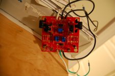
At the top of the amp board, the section with 4 connections marked O/P
I am guessing the most left goes to p-channel board to Gate
The 2nd from the left goes to p-channel board to O/P
The 3rd from the left goes to n-channel board to O/P
And the 4th to n-channel Gate
Does this sound correct?
The +Ve and Ground on the p and n channel boards come from the power board.
Next question: what does the `link` do on the amp board? For F5Tx?
Thanks.
Last edited:
Outer holes are output to gates. inner holes are feedback points from output board. Will only need to use one of feedback holes, as they are connected. Ve+ and Ve- are from PSU board. The wiring gets hairy. Be careful and ask questions.
You must connect link and ground if not using as balanced. If balanced, you would connect link to other boards link. THis i where you would have negative and positive halves of the input signal.
You must connect link and ground if not using as balanced. If balanced, you would connect link to other boards link. THis i where you would have negative and positive halves of the input signal.
Attachments
Last edited:
IF you want to be uber careful, you can power up FE boards before attaching output boards. THis way if something is not right, you dont burn anything. With high IDSS Jfets like you have, the outputs will come up hot, so trim the pots down before powering up if you dont go safe or you dont have a variac.
Just to confirm:
Looks like each of the the output boards have places for 4 output FETs? Or did I read it wrong? The reason that I am asking is because I was told that I need 2 sets to build a F5T V3 [with one front end board (for the cascode)left over], which has 8 FETs per channel. So does it mean that I am only using one side of each of the output board? It actually would fit my plan perfectly since I want to place 4 output FTEs per heat sink and I have 4 for 2 mono-blocks.
Any comments will be appreciated.
Regards,
On each output of the store board, there is a place for two mod fets and two diodes. For v3, you would put two boards of like pairs one sink, two boards of opposing pair on opposite sink, and drive with single FE board. You then have a V3 monoblock
Buzzforb,
Thank you for the clarification!
Regards,
would be nice to see the schematic, bom, and the connection diagram, unless that is indicated in the schematic - for these particular boards. Someone asked me to take a look at what was available, and while his needs probably are best met by the F5c since they are not currently available looking at these.
I'm a bit confused about it. Not the schematic in NP's pdf, but by this 4 board layout...
More info would be good.
_-_-bear
I'm a bit confused about it. Not the schematic in NP's pdf, but by this 4 board layout...
More info would be good.
_-_-bear
I'm a bit confused about it. Not the schematic in NP's pdf, but by this 4 board layout...
More info would be good.
Me too. Like to see a hook up diagram.
Thx
I can take pics of mine, if it would help.
That would be helpful.
Well, is this basic layout discussed anywhere, like in another thread??
I have taken a look around at the various F5t threads and have not come across it.
What does the small board do? Does it hold only the two JFets and associated parts? Why the 4 boards and not 2?
I actually own a set of Tea-Bag's boards, so I'm not totally unfamiliar with the F5t, but I'm a bit confuzered at this point. (maybe I can figgureit out by looking at the higher res images of the boards...)
_-_-
Edit: the res on the high res is barely enough to see the details. I don't quite see it...
feel a bit dense, but it's hard to tell if the "driver" board is splittable or not for example, and if it works as a stand alone amp, or how ur supposed to use the other boards.
Personally, I feel nervous about stability and possible parasitic issues with there being much distance between the jfets and the outputs...
Anyhow, more info would be mo' bettah...
Last edited:
What does the small board do? Does it hold only the two JFets and associated parts? Why the 4 boards and not 2?
With the boards from the DIYAudio store, you can make mono-blocks. For example, you can have a mono amp with P channel mosfet on one heat sink and N channel fets on the other. Keep in mind that this would work for a standard chassis, like the 5U chassis in the DIYAudio store. You could also, providing you had a large enough heatsink, install both N and P channel output boards on 1 heat sink.
There's flexibility in using these boards, if you choose to use it.
I don't know how Tea-bags boards work, but I would think they are simular.
My problem is, I'm not sure where the outs from the driver board connect to the outputboards and where the ins and outs are located exactly. I see them, but I'm a little confused and reluctant to just make connections on a guess.
Ah, I see, you mean single chassis - 2 heatsink "monoblocs"?
Teabag's stuff is all on one single board, so you can make a monobloc, but it's going to be all on one heatsink. That's fine for me, since I would build a different profile than the standard chassis with the left right heatsink set up.
It my opinion that this is not as efficient in terms of utilizing the heatsink as it might be. Vertical is how I am going, myself. Of course that yields a different shape amp, and isn't going on a rack so well, but I don't like racks/shelves that much, and never put my amps on them anyhow...
_-_-
eitherway, I'll tell my friend to wait a bit, and hope the Cviller boards come up again...
- Home
- The diyAudio Store
- F-5 Turbo boards