I've built 2 ACAs and 1 Aleph J.
All of them sounded glorious from the moment after I had them biased and then put music through them.
If there was a "burn in" improvement, sorry - I missed it.
My guess is that you'll enjoy the same experience with an F5.
All the best.
Those who are lucky enough to have built and enjoy an F5 are welcome to put me straight.
FWIW, heat doesn't rise. Hot air does. Heat spreads out uniformly in all directions.
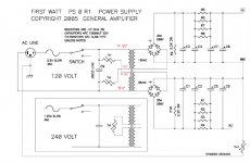
The 2K2 resistors are bleeders (for discharge when the amp is turned off). R5 through R8 are the 'R' in the middle of a CRC filter, which is much more effective than a C filter. A C filter largely just shifts the phase and frequency; an RC filter actually damps the waveform.
Cheers,
Jeff.
Just to follow up on this i did a little reading on crc filters, it appears that the larger the size of the resistor the more it damps the waveform.
Would using high esr capacitors help damping in this position?
Also what do you think about using lead or tin based cables as these have high resistance rather than the usual copper to have a resistance effect and mimic the use of the resistors or perhaps to replace them entirely.
Thanks
Last edited:
Thanks! Why do you think nelson chose these resistors, 4 in parallel, giving 0.1 ohm total resistance.
In most tutorials i have read the resistance is usually a lot higher with crc filters.
2. Maybe to do with power loss if a higher resistance is used, but what would be the effect of a one ohm resistor in this location, would it give smoother dc.
In most tutorials i have read the resistance is usually a lot higher with crc filters.
2. Maybe to do with power loss if a higher resistance is used, but what would be the effect of a one ohm resistor in this location, would it give smoother dc.
There parallel resistors are effectively a 0.12ohm 12W resistor.
More resistance and the voltage drop gets too big, as does the thermal load. This is a high-current Class-A PSU after all.
(4) 0.47R 3W resistors are inexpensive and saves having another stock number in his wearhouse.
More resistance and the voltage drop gets too big, as does the thermal load. This is a high-current Class-A PSU after all.
(4) 0.47R 3W resistors are inexpensive and saves having another stock number in his wearhouse.
Would using high esr capacitors help damping in this position?
High esr is best avoided. High esr results in high ripple and also high temperature. For a typical amplifier power supply low esr is desirable.
Good point, just that 0.12 ohm seems very small for a crc filter. According to the tutorials i have read i have never seen a value this small. I can't see it having much of an effect on smoothing the waveform.
Would moving up to a one ohm give smoother dc. Or is this nitpicking, would there be not much of a difference. I realise it would create more heat and reduce power, could use a bigger transformer.
Thanks
Would moving up to a one ohm give smoother dc. Or is this nitpicking, would there be not much of a difference. I realise it would create more heat and reduce power, could use a bigger transformer.
Thanks
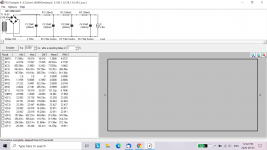
Here are simulations for CRC and C.
44,000uF - 0.12R - 44,000uF gives 68mV ripple.
88,000uF gives 225mV ripple.
44,000uF - 1R - 44,000uF gives 10mV ripple.
So 0.12R drops the ripple substantially compared to no R. I believe that typical First Watt power supply uses 0.12R in the CRC power supply.
The 1R gives the least ripple, as expected. However, the 1R does drop the voltage substantially. Another con is that the higher R will cause the output voltage to vary much more with current variation than with 0.12R.
BTW, I just threw in some numbers in the simulation to illustrate the differences in power supply filtering and may not represent the actual power supply requirements for the amplifier.
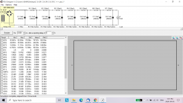
Attachments
Thanks. Could you please try 2 or more 0.1 ohm resistors and put up the ripple results.
At the moment it is a ccrcc filter, would love to know the effects on ripple with crcrcrcr, or ccrcrc. Each successive resistor is supposed to lower ripple and using small 0.1 ohm resitors may not affect the output voltage and current as much as a big one ohm, i'm wondering by how much.
Thanks
At the moment it is a ccrcc filter, would love to know the effects on ripple with crcrcrcr, or ccrcrc. Each successive resistor is supposed to lower ripple and using small 0.1 ohm resitors may not affect the output voltage and current as much as a big one ohm, i'm wondering by how much.
Thanks
Last edited:
Well, the First Watt power supply CRC is 30,000uF - 0.12R - 30,000uF.
According to NP, the F5 is "very quiet, about 60 microvolts or so".
http://www.firstwatt.com/pdf/prod_f5_man.pdf
By the way, the 60 uV is noise at the amplifier output, not PS ripple.
According to NP, the F5 is "very quiet, about 60 microvolts or so".
http://www.firstwatt.com/pdf/prod_f5_man.pdf
By the way, the 60 uV is noise at the amplifier output, not PS ripple.
Last edited:
Thanks for the replies, much appreciated.
The ripple is 225mv without the resistors and 68mv with resistors, how much of an effect would that differnce have on the sound quality. Would this difference change the sound enough to be audible. Trying to figure out how valuable the resistor implementation is. What difference would i hear as far as sound emerging from the speakers.
The ripple is 225mv without the resistors and 68mv with resistors, how much of an effect would that differnce have on the sound quality. Would this difference change the sound enough to be audible. Trying to figure out how valuable the resistor implementation is. What difference would i hear as far as sound emerging from the speakers.
Last edited:
Excessive ripple in the power supply may be perceived as 120Hz hum and harmonics (for 60Hz line). Whether it is deemed excessive and audible will depend on the sensitivity of the speaker connected to the amplifier and also on the ability of the amplifier to deal with power supply ripple. Class A push-pull circuits inherently reject power supply ripple and noise but single ended circuits do not.
The F5 is push-pull so it can reduce the audible effects of the power supply ripple and noise.
As for speaker sensitivity, that is dependent on your choice of speaker.
As mentioned previously, NP said that the F5 is "very quiet". Its power supply CRC is 30mF - 0.12R - 30mF. A CRC of 44mF - 0.12R - 44mF with its 68mV ripple has lower ripple so it should be even quieter. As a minimum, I would suggest building with the standard FW F5 CRC power supply. You can increase the capacitance if you want an even quieter supply.
One other thing to consider - a quiet power supply design and amplifier circuit does not guarantee a quiet amplifier. Many elements of amplifier construction, including grounding technique, wiring layout and routing, component placement, and transformer orientation and location, can all create noise in an amplifier if not done correctly.
Not since the store started selling some NOS Toshiba Jfets. All the other parts are easily attainable. It's a fantastic amp. There's also a parts kit for that amp—minus the Jfets.

- Home
- The diyAudio Store
- diyAudio F5 Build Guide