Sorry it's taken so long, but I promised I'd post a pic and subjective findings.
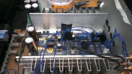
Firstly I apologise for the bodgy nature of the build. I (partially) hollowed out an old Marantz PM55SE to get a temporary chassis. A proper one is still planned but it's non-essential so is in the queue.
The strangeness you can see where the input switching relays ought to be is a power supply for the Lightspeed, which is the strangeness you can see in place of the volume pot. I initially tried sharing a 5V supply with the muting relay, which was the point of going 5V there, but it really didn't like it. So it's a separate tap from the rectified DC input. Getting 5V down from the 18V (iirc) sure put some heat into the regulators, but as you can see I dealt with that by using pairs of board mounted heat sinks, inverted to stand them clear of the boards. They're not too heavy so should be fine so long as I remember not to post it anywhere.
Right, subjectives. For context my other components are a Leema Antila CD player, MC2 MC450 amp, and ATC SCM19 Mk2 speakers. My other outboard pre-amps ones are a Primare P30, a Lightspeed and a MiniDSP DDRC24. It was mostly compared to the MiniDSP. This has caused me some future issues as I'm looking at converting to active in the future and needed the DSP. I can't use it now. I just can't go back. Everyone has their demons they chase through their systems but my main one was a slight graininess/harshness/glassiness in the upper mid-range. It's gone now. The improvement in detail and clarity while still expelling that hardness and sounding smooth and natural, is something I thought I'd never achieve. As such I find that the Mez especially shines with acoustic material. It may be me, I need to do some more A/B, but I wonder if the bass has lost a little definition. If so I suspect that's down to the impedance of the Lightspeed. More playing is needed.
Finally, I think I found a flaw in the BOM. It suggests two 300 ohm resistors if using a 5V relay. I found that it needed just one to get the right voltage.
Attachments
Congratulations. Nice results. Happy that you like it. You don't use an input relay I think? When using an input relay also, there will be double the now drop across that resistor. The output delay relay & one selected input relay will be engaged all the time, thus half your now Ohms value should be adequate then. Hence the place for another 300 Ohm in parallel. Maybe 2x250R or 2x270R would drop the 12V line closer to 5V nominal feed. There are tolerances but each coil should be drawing about 28mA at 5V (178 Ohm load). Such relays also have 3.75V must operate voltage spec so feeding dead on 5V to them isn't necessary anyway. For 12V relays no resistors are needed, just a jumper link in one of their places as the note on the board reminds.


Yeah, I wanted to try without the lightspeed as it was exhibiting some rather extreme non-linearity in volume, which made me concerned about compatibility with my sources. I'd like to measure both ways but am under no illusion that THD+N will go up.
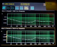
Apologies for the crudity of the tests there. It was a quick one, as evidenced by the lack of smoothing. We (it's not my test gear) have tentative plans to do a proper and complete set of tests from which accurate specifications can be derived. Of course that will include distortion vs. amplitude. Have tests ever been done by anyone else? If so it would be interesting to compare.
The conditions of the above were unity gain and 0dB / 0.775V. Also it wasn't warmed up, if that might make a difference.
Last edited:
There was a set done on a Tek analyzer by Spanish member Ramallo many years ago. Details about the THD sweep level were not given, only what was on a picture. Those curves were more zig zag and somewhat worse in % than yours on the AP station. His was a full inputs wired and boxed unit so it could also have its own peculiarities of shielding, transformer proximity, grounding.
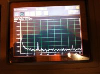
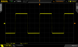
My prototype's 1kHz spot frequency FFT done on an EMU interface ten years ago was about 0.001% THD+N at unity gain as yours shows there and in many other frequencies nonetheless. The second picture is the PSU's hum on the Mez board. The third is 100kHz square wave response done with a better scope at a later point by me.
My prototype's 1kHz spot frequency FFT done on an EMU interface ten years ago was about 0.001% THD+N at unity gain as yours shows there and in many other frequencies nonetheless. The second picture is the PSU's hum on the Mez board. The third is 100kHz square wave response done with a better scope at a later point by me.
Attachments
The PCB board for this project is sold out. ETA for next batch?
Hello,
I am quite interested in building this preamplifier, as my main music source is digital, and has a fairly strong output signal of 2.6V. However, there doesn't appear to be any PCB boards in stock right now on the The diyAudio Store - DIY amplifier kits, chassis, and parts website. Do you have any idea when the PCB boards for this will be available again?
Kendra
Very recently Jason (the diyA admin) told me he will be ordering a new batch to be made. It will be the "Ten Years After" re-issue for which I wrote and sent him a two page PDF doc with modern BOM and few quick notes. Has manufacturer part numbers I selected for good proper components that don't cost too much and are readily available in major stockists. Nichicon for audio caps and 50ppm-100ppm Dales I mean, no slouches. Also specific transformer examples and specific replacement relays to the OMRON originals. Plus a fairly consistent LED part number that will not cry for VF matching.
This board re-issue has rearranged mounting points distances made compatible with the perforated extra baseplates of the diyA store's Hi-Fi 2000 chassis series. Jason measured those and moved the mounting holes accordingly. But I gave it a little touch too. I changed its Vrefs to be like in the Hypnotize i.e. to run same bias current for the 5X LEDS per side when all factors are the same. Since nobody ever uses it with no sinking at very low MOSFET current anymore, the older asymmetrical Vref current arrangement lost its voicing role for that mode. Now it will be recommended with 2X18Rset per side only, yielding 180-200mA CCS.
This board re-issue has rearranged mounting points distances made compatible with the perforated extra baseplates of the diyA store's Hi-Fi 2000 chassis series. Jason measured those and moved the mounting holes accordingly. But I gave it a little touch too. I changed its Vrefs to be like in the Hypnotize i.e. to run same bias current for the 5X LEDS per side when all factors are the same. Since nobody ever uses it with no sinking at very low MOSFET current anymore, the older asymmetrical Vref current arrangement lost its voicing role for that mode. Now it will be recommended with 2X18Rset per side only, yielding 180-200mA CCS.
Do you have any idea when the PCB boards for this will be available again?
Kendra
In about four weeks from now
")
I bought the recommended Antek Transformer too.
Looks like mouser has most of the parts I need.
I also need to order parts for my Honey Badger and Aleph Mini builds. [emoji3]
Just need a Phono and DAC project and I'm done[emoji41]
Although the LSK170B groups of eight from the store can be consistent enough (one review mentions within 2mA) for many applications, I wouldn't think you could be so lucky to find a matched quad within 0.1mA IDSS between just eight. It's either the DIY store will ever offer a minikit with preselected LSK170B quad for the Mezmerize signal path and six non selected for the rest of its circuit, or you should use six out of those eight for the PSU only and keep two as spares. You can mix NOS Toshiba 2SK170BL in any PSU area position but for the in line quad located at middle board use single brand tightly matched for IDSS. Those are the two channels signal pairs responsible for THD and DC offset.
Previous builders here may recommend trusted vendors where they sourced their NOS Toshiba quads also.
Previous builders here may recommend trusted vendors where they sourced their NOS Toshiba quads also.
Unfortunately not. They have high IDSS and they will torture the LEDS. Plus they will become unreliable due to pushed self-dissipation for their small TO-92 package because this circuit runs them in full IDSS at high enough VDS. Also their VGS (OFF) will be high for a couple of key positions in the PSU. The higher the IDSS range the higher the pinch off voltage range in JFETS.

Choose something with significantly more current reserve than a B1 to drive 35 ft interconnect. All that B1 has is 7-8mA from its signal path JFET IDSS. The cable's capacitance demands more current as the frequency gets higher. The longer the cable the more its capacitance.
- Home
- The diyAudio Store
- Mezmerize B1 Buffer Preamp