For sale: Compact, low distortion, easy to build LM3886 PCBs
For sale are compact, low distortion, easy to build PCBs for an LM3886 amplifier.
Should you be interested in the SMT version, please send me a PM.
The through hole version (as well as the PCBs for a bunch of my other projects) is available at HiFiOcean.com for only US$9 per pair (one board is for one channel; a pair makes a stereo amplifier) plus shipping. I am also offering it on eBay.
For sale are compact, low distortion, easy to build PCBs for an LM3886 amplifier.
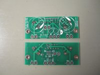
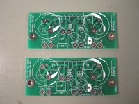
- Compact: only 2.9x1.2in (one channel), with the same mounting pattern and a similar layout to the boards previously sold by ChipAmp.com (which, sadly, seems to be out of business, and to which I am not related).
- Low distortion: advanced signal routing offers superior performance. THD+N is less than 0.002% when driving 18Vrms into 8ohm with an unregulated power supply. The distortion spectrum is "soft", with a low level of higher order harmonics. The high frequency linearity is also excellent.
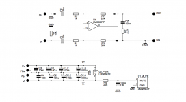
- Easy to build: The schematic is very simple, with only a few parts and nothing exotic. A more detailed description, including the schematic and BOM, can be found in the posts #2 and #3 below.
- The through hole version is a simple non-inverting LM3886 amplifier.
- The SMT version uses 0805 parts and can be used as inverting, non-inverting, or balanced differential input amplifier.
Should you be interested in the SMT version, please send me a PM.
The through hole version (as well as the PCBs for a bunch of my other projects) is available at HiFiOcean.com for only US$9 per pair (one board is for one channel; a pair makes a stereo amplifier) plus shipping. I am also offering it on eBay.
Attachments
Last edited:
Schematic and BOM - through hole version
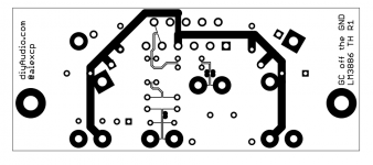
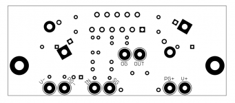
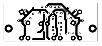
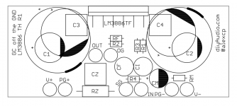
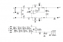
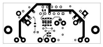
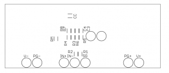
Attached are the schematic, PCB artwork and the BOM for the through hole version.
Attached are the schematic, PCB artwork and the BOM for the through hole version.
Attachments
Schematic and BOM - SMT version
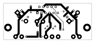
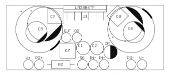
Attached are the schematic, PCB artwork and the BOM for the SMT version. Note that the inverting input must be grounded or driven by a low impedance source (e.g. a local opamp is ok but a long cable is not) to prevent instability.
Attached are the schematic, PCB artwork and the BOM for the SMT version. Note that the inverting input must be grounded or driven by a low impedance source (e.g. a local opamp is ok but a long cable is not) to prevent instability.
Attachments
A note on power supply
The PCBs are designed to work from two isolated power supplies (e.g. 35V + 35V) connected by four wires (V+, PG+ for the positive rail, V-, PG- for the negative). They will work with a bipolar supply with a common connection shared by both rails (e.g. three wires V+, V-, COM), but the distortion will be higher.
For my tests, I used a 100VA 2x24V toroidal transformer and a ChipAmp.com PSU board, consisting of two 4x MUR820 bridge rectifiers and two 22,000uF filter capacitors.
- Status
- This old topic is closed. If you want to reopen this topic, contact a moderator using the "Report Post" button.