The order of components connected in series doesn't matter.
On NP's schematic, the order is different from that on NP's PCB. My PCB closely follows NP's PCB, but my schematic and the board are in sync, so the order on my schematic is different from that on NP's schematic.
Again, this does not matter from the electrical standpoint.
On NP's schematic, the order is different from that on NP's PCB. My PCB closely follows NP's PCB, but my schematic and the board are in sync, so the order on my schematic is different from that on NP's schematic.
Again, this does not matter from the electrical standpoint.
Pass DIY Addict
Joined 2000
Paid Member
Hey Alex,
I'm in the process of re-doing my A40's with your newer boards. I previously used your purple osh park boards with the LM334, which worked out great.
Just curious about using J113 for the front end current source, I simmed about 280R for the J113 resistor, which gives roughly 3mA, I know it'll probably need adjstment real world. Just curious if thats close, and that I simmed it correctly. A note in the datasheet stated the LM334 is 4x noiser than a transistor, hence the reason I'd like to go with a J113 there. Also curious if you or anyone has any experience with using the J113 vs LM334 in this position.
thanks,
John
I tried a few options and did not hear nor measured any difference.Just curious about using J113 for the front end current source, I simmed about 280R for the J113 resistor, which gives roughly 3mA, I know it'll probably need adjstment real world. Just curious if thats close, and that I simmed it correctly. A note in the datasheet stated the LM334 is 4x noiser than a transistor, hence the reason I'd like to go with a J113 there. Also curious if you or anyone has any experience with using the J113 vs LM334 in this position.
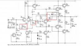
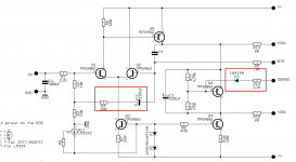
Integrated current sources such as LM334 or IXCP10M45S are convenient because the datasheet gives you a formula for the resistor value that will give you the desired current. For example. for LM334:
(where VR=64mV@298°K and n =14).
With J111/112/113 or any other depletion mode FET in that position, R9 ideally would need to be matched to the specific transistor to set the current through D1-D2 at about 3mA at the correct Vds. The reason is that Vgs(off) and Idss vary widely:
In my testing with Vds=28V, a randomly selected J113 provided 3mA with a 360 ohm resistor (not too far from your simulated 280 ohm); J111 - with 2.4kOhm; DN2540 - with 470ohm.
Note that the current through D1-D2 is not that critical as long as it is stable and reasonably quiet. If it is not 3mA but 5mA or 10mA, it will be just fine. Because of that, you can just plug in a resistor with a reasonable value, such as the one I measured.
