These have sold to the member who responded earliest. I thank all of you for looking. I'll be posting more goodies in the days ahead.
To my friends outside the US, I'm sorry but shipping out of the country has become too much of a hassle for me, especially on small, bargain priced items.
Thank you,
Mike
To my friends outside the US, I'm sorry but shipping out of the country has become too much of a hassle for me, especially on small, bargain priced items.
Thank you,
Mike
This amp would be easy to convert to an Oddblock type of SIPP output....just replace r5-r6 with an LM317hv set as a CCS to the total idle current of both power tubes and then break the circuit before r7 and connect r7 to ground...if they are point to point it would be an easy conversion and I bet they would improve greatly....
Just a thought....
Well, on second look I didn't see the bias resistors for the gain stage...may be a little more complex, need to think about it....
Just a thought....
Well, on second look I didn't see the bias resistors for the gain stage...may be a little more complex, need to think about it....
I'll be interested in what you do with those. I have a pair i got for parts too.
dave
At the moment playing jazz!
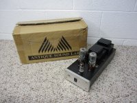
") I powered the amps up on my variac.They played, but distorted, 60Hz hum and the tubes wouldn't bias. I replaced the signal coupling caps, (with Russky K40 PIO's), driver electrolytic caps and re-did all of the grounds. As long as the trannies are good, not much to break/fix.
I powered the amps up on my variac.They played, but distorted, 60Hz hum and the tubes wouldn't bias. I replaced the signal coupling caps, (with Russky K40 PIO's), driver electrolytic caps and re-did all of the grounds. As long as the trannies are good, not much to break/fix.That seemed to fix them, but I have ordered replacement B+ power supply coupling electrolytic caps and will replace those when they arrive. All of the stock caps were really poor quality.
Pretty simple design, the schematic helps understand. Other than maybe changing signal resistors or adding a PS choke. I will leave them alone. The PCB's aren't the best so I don't think they will hold up to many solder cycles.
They actually sound pretty nice, even with the PIO's burning in. I will put about 40 hours on them before I do anything else. I have them playing into a mule OB project with Audio Nirvana Cast 8's and Eminence Alpha 15's. At the exorbitant price Mike got for these, I am pretty happy.
Anyone know the factory recommended bias? I searched the web, seems that about .325V is in the ballpark. But would be nice to know the design spec.
Cheers,
Geary
At the moment playing jazz!
That seemed to fix them, but I have ordered replacement B+ power supply coupling electrolytic caps and will replace those when they arrive. All of the stock caps were really poor quality.
Pretty simple design, the schematic helps understand. Other than maybe changing signal resistors or adding a PS choke. I will leave them alone. The PCB's aren't the best so I don't think they will hold up to many solder cycles.
They actually sound pretty nice, even with the PIO's burning in. I will put about 40 hours on them before I do anything else. I have them playing into a mule OB project with Audio Nirvana Cast 8's and Eminence Alpha 15's. At the exorbitant price Mike got for these, I am pretty happy.
Anyone know the factory recommended bias? I searched the web, seems that about .325V is in the ballpark. But would be nice to know the design spec.
Cheers,
Geary
Yea yea, rub it in
Mine is a total rebuild. One of the chassis warped and whiped out the PCB
dave
Dave,
That's too bad, but, perhaps, not fatal. Simple circuit. P2P wiring is likely an improvement over the board. I would do both amps, though. Also, you might try to get a replacement board from Tash Goka <divergent@divertech.com>, the distributor.
Actually rather nice sounding with some selective parts replacement. I am more a SET type, but these have a seductively sweet sound.
Cheers,
Geary
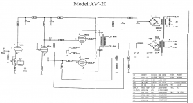
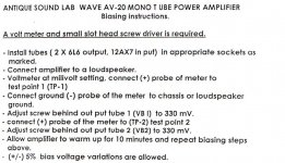
I received an electronic doc with the schematic and biasing instructions. I 'photoshop'd' to make 2 docs and, hopefully, better image quality.
Short version on biasing....330mV.
Cheers,
Geary
Short version on biasing....330mV.
Cheers,
Geary
Attachments
Dave,
That's too bad, but, perhaps, not fatal. Simple circuit. P2P wiring is likely an improvement over the board.
It would. And give me an opportunity to do a different circuit, i'd rather have a CSSed LTP on the front and cathode bias (or LED stack) on the outputs.
dave
I received an electronic doc with the schematic and biasing instructions. I 'photoshop'd' to make 2 docs and, hopefully, better image quality.
Short version on biasing....330mV.
Cheers,
Geary
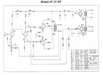
I want to point out that the schematic that I received from the distributor is for the AV25. Apparently the only difference between the AV20 and the AV25 is the power transformer. The voltages for the B+ are likely higher to get the higher wattage. The only component value difference I could find was R43 in the negative bias PS. AV20 = 5.6k AV25 = 1.5k.
Geary
- Status
- This old topic is closed. If you want to reopen this topic, contact a moderator using the "Report Post" button.