I just downloaded aKaBaK also, it seems prety nifty.
If anyone here has compiled a basic list of scripts to represent various audio entities I would love to see them. The don't provide many examples in the PDF.
I haven't had much luck getting a simple vented box working yet I think looking at the script dirrectly may be and easier way to learn, than punching in values and dimensions and hoping it turns out right.
Ok thanks guys,
Time to go make sure a DJ didn't melt my BS-212 subs.
Re: K couplers
You're missing the point talking about high frequency reflections etc. This is a subwoofer. I know most people summarily dismiss the K (most I suspect without having heard one properly implemented) but the design does have its merits, ..but I digress.
The point of the k-slot is to smoothen the transition from the horn to the air, hopefully reducing ripple. That's what Bill Woods (RCA Fan on AA) did with his K-Slot BLH.
I'm not looking at any bandwidth gain with the k-slot (it would need to be much much longer at these frequencies) but merely to optimize the profile of the (undersized mouth)
Will it work?.. I guess we'll never know until someone tries it (maybe me if I can ever find some free time in the near future).
sumsound said:For some reason I think you would get more problematic reflected high frequency energy behind the exponential slot in the K coupler, than any improved driver loading in those ranges. I'm sure one would have lots of cancelations in the upper ranges.
I think the guy who is thinking of incorporating a K coupler into a Tapped horn design is missing the point of what a K is coupler is supposed to acomplish (Not that I really understand, but I think its a bunch of esoteric sillyness). A subwoofer doesn't need extra HF loading, and its not going to do anything for LF extension.
You're missing the point talking about high frequency reflections etc. This is a subwoofer. I know most people summarily dismiss the K (most I suspect without having heard one properly implemented) but the design does have its merits, ..but I digress.
The point of the k-slot is to smoothen the transition from the horn to the air, hopefully reducing ripple. That's what Bill Woods (RCA Fan on AA) did with his K-Slot BLH.
I'm not looking at any bandwidth gain with the k-slot (it would need to be much much longer at these frequencies) but merely to optimize the profile of the (undersized mouth)
Will it work?.. I guess we'll never know until someone tries it (maybe me if I can ever find some free time in the near future).
That sounds a little redundant, since a horn effectively couples the driver to the outside air.
As some people put it the horn is an accoustic transformer.
The driver alone is typicaly ill equiped to couple to the air especially at extra low frequencies where air viscosity no longer a factor and the driver becomes incapable of displacing enough air to keep realatively flat spl bandwidth.
I can see that the K-coupler probably has a little bit of a coupling effect, but probably not as effective as a circular exponential horn. I'd like to see some good measurements of the K coupler with and without the exponential coupling slot.
I also wonder what dirrection does the coupled energy propagate? For some reason my mind keeps telling me its all going to propagate toward the plane of the slot.
I guess its more a wideband resonant slot?
I can't say that I have ever experienced a K-coupler. So I wouldn't know what to expect.
Antone-
FWIW here's a two-tone test of a Beta 15CX swapped between a beat up homemade Karlson 15 and a reflex ~equal to the K's rear chamber. Both have Z minimum about 50Hz - are/were K merely advanced bandpass?
http://img474.imageshack.us/my.php?image=dop151wm4.jpg
a simulator which can handle TH might help with K although K didn't have much height
hey Don Bunce - pretty cool recycling to make a folded TH - do you have means of quick sweep graph?
http://img474.imageshack.us/my.php?image=dop151wm4.jpg
a simulator which can handle TH might help with K although K didn't have much height
hey Don Bunce - pretty cool recycling to make a folded TH - do you have means of quick sweep graph?
rick57 said:post 188
Greets!
You're welcome!
Well, if you learn all the electro-mechanical-acoustic physics like the pioneers of prosound did, then you can.
")
Yep. You must be using WinISD or similar, which can't come even remotely close to ~accurately simming this cab's response.
Depends of course, but basically you'll have a lot more linear dynamic headroom with acoustic gain and if the latter is damped enough, then it has much lower distortion on average to boot. If there's enough Xmax/power handling, then the max flat alignment will in theory be fine, but there's naysayers, so as always YMMV.
Right, there's a point of diminishing SD:vent area where it takes more pipe action to benefit from boundary gain.
GM
sumsound said:
I'm not sure what you bass that statement on, I have done extensive modeling on many drivers.
I haven't totally digested what Tom has said about the Tapped Horn Drivers FS Higer than the Horns Low Cut. But perhaps the rules are different in a TH.
The statement that the driver doesn't have enough mass doesn't make sense to me either. It has enough mass that its Fs is around 21Hz. The More mass you add to the driver the Weaker the BL, or motor strength. So your caught chasing your tail. Think about it.
I don't think correctumundo is an accurate response to the posters assertion.
I still belive the Lab12 is one of the best subwoofers you can buy for the price.......
Greets!
From building horns, I didn't have the benefit of the powerful simming and measurement programs available today.
A horn acoustically mass loads the driver, lowering its Fs, so normally a rear compression chamber is used to push it back up so that it has a stable work 'platform' to drive the horn efficiently. In a BLH or tapped horn with the driver near/at the terminus, there's no rear chamber to shift it back up. With all the modelling you've done, I don't understand why you're not aware of this. Or have you only modeled simple vented and/or sealed alignments?
Well, I've not only thought about it, but I've built all manner of alignments to see how they performed/functioned and if you think about it, you'll see you answered your own question.
BTW, supension compliance is equally important in determining Fs: ((1/Pi)/2)*((1000/(Mms*Cms))^0.5). Well, I do, so we'll have to agree to disagree.
I agree the LAB12 is an excellent driver for certain alignments, that was never in dispute. Bottom line, you want the right driver specs for the intended alignment, or in the Matterhorn's case, one that was 'close enough'.
GM
Don Bunce said:I,too, am curious as to what that statement was based on.I have been using 2 LABhorns for some time, and the results so far with the tapped horns I built would indicate that the LAB12 driver is an excellent choice for a tapped horn.
Greets!
I'm sure it is for certain alignments, but a more massive one would be better for others. Anyway, I'm not convinced yours is all that optimized, but with no measurements............ Anyway, I see some folks now have TH simming capability, so they can quickly figure out what's what WRT how mass, etc., affects TH design/performance and how well yours works.
GM
I will be the first to admit that this is not an optimized design.Since I have the LAB12 drivers,it seemed to be a good place to start.I was surprised that it worked this well on the first try.As I mentioned before,I thought the folded version sounded better.I placed the original horn in the same corner next to the folded one.It wasn't the room,the folded one sounds better.The straight one seems a bit loose and boomy is comparison.Maybe the bracing isn't adequate...
If anyone is able to sim this,that would be great.Use the 14" wide dimensions.
The LAB12 driver may not be optimum(according to theory)but it is doing a fine job in this horn.It tromps the LABhorn below 30 hz,and pretty much holds even above that.Not as efficient ,but still more than enough for home use.I'm going to build four of them.hehehe...
Here's a response curve,pink noise full range into the folded horn,measured at my listening position with a Behringer 8024 ultra curve pro with a DBX mic.
http://img260.imageshack.us/img260/408/foldedhornsraighthorn00ow2.jpg
Here's a photo of the horns in my room.
http://img292.imageshack.us/img292/7686/foldedhornsraighthorn00cy5.jpg
http://img292.imageshack.us/img292/7686/foldedhornsraighthorn00cy5.jpg
Freddyi,
My ceiling is 94"
No George Wright,but got Ken Griffin on 78.
http://img174.imageshack.us/img174/6324/kengriffin0071tr7.jpg
My ceiling is 94"
No George Wright,but got Ken Griffin on 78.
http://img174.imageshack.us/img174/6324/kengriffin0071tr7.jpg
hey Don - I can get into moods to listen to about 4 hours of KG - gotta have "Glow-Worm" = masterpiece
got 100's of T-organ cd but no subwoofer yet - you should have George - there's 3 inexpensive cd which are fab plus Banda's lineup
here's RTA direct from one of the cheap cd and this cut doesn't punch like Washington Post March
http://img354.imageshack.us/img354/7950/gwbjpgmw0.jpg
who's gonna be the first to sim or kluge-sim your TH? - if I could figure out a real kluge on AJ then would give try.
Freddy
ps U also need to suffer the karlson-kurse (?) = way to make noise
maybe you can use those TH with the acoustic phonograph - or maybe build long extension for the acoustic like Percy Wilson
GM
I'm still not convinced that Lack of Mass and motor strength is the Lab12's Weakness. If anything I would think it was its xmax. It does have quite a loose suspension to acheive its Fs, besides the mass of the driver, but wouldn't adding a beefier suspension, raise Fs, and robbing some Sd? More Mass must be added to lower Fs, BL changes etc.
Would a lead piston of equal or greater mass on a comparably powerful motor make a good LF transducer?
I have played with a little horn modeling but not much yet.
I have just started to figure out akaBak. They really need to make a set of options for the airmass calculator, doing a Duct transition to another duct is a lot of work, unless you have a nice calculator or Math Program.
Here are the first two graphs I generated of a TH with the Lab 12 Driver tapped a 1/4 way into the horn.
The first graph TH_1 I didn't generate a paralell path for the Rear wave to travel back down the horn.
The Second one TH_This I duplicated many of the entities and paralelled them back towards the throat.
I used ducts almost exclusively, and used air mass's for the bends and transitions.
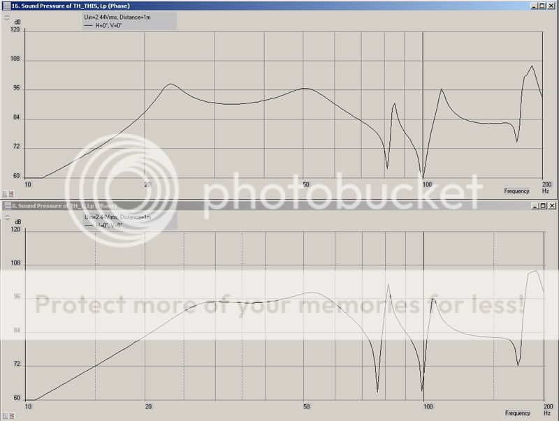
The TH_This graph looks an awful lot like Cowens, graphs of tapped in at 1/4 horn path.
Anyone have any thoughts on the possible accuracy of what I generated?
Antone-
I'm still not convinced that Lack of Mass and motor strength is the Lab12's Weakness. If anything I would think it was its xmax. It does have quite a loose suspension to acheive its Fs, besides the mass of the driver, but wouldn't adding a beefier suspension, raise Fs, and robbing some Sd? More Mass must be added to lower Fs, BL changes etc.
Would a lead piston of equal or greater mass on a comparably powerful motor make a good LF transducer?
I have played with a little horn modeling but not much yet.
I have just started to figure out akaBak. They really need to make a set of options for the airmass calculator, doing a Duct transition to another duct is a lot of work, unless you have a nice calculator or Math Program.
Here are the first two graphs I generated of a TH with the Lab 12 Driver tapped a 1/4 way into the horn.
The first graph TH_1 I didn't generate a paralell path for the Rear wave to travel back down the horn.
The Second one TH_This I duplicated many of the entities and paralelled them back towards the throat.
I used ducts almost exclusively, and used air mass's for the bends and transitions.
The TH_This graph looks an awful lot like Cowens, graphs of tapped in at 1/4 horn path.
Anyone have any thoughts on the possible accuracy of what I generated?
Antone-
whats the longest path on Cowan's 30Hz?
FWIW here's how AJ looks at stuff as BLH with a kluge (-dl = tip to try from Pit)
Don's horn
William's horn
FWIW here's how AJ looks at stuff as BLH with a kluge (-dl = tip to try from Pit)
Don's horn
An externally hosted image should be here but it was not working when we last tested it.
William's horn
An externally hosted image should be here but it was not working when we last tested it.
I'm not sure what williams path lengths are.
I just took the outer dimensions of the DTS-20 and started throwing in sections much like Walts "Stepped Horn"
Aj sure looks like its a lot easier to deal with that akabak, but I think akabak is a much more modular aproach. I'm not familiar with Aj. Is it freeware or Licensed software, or something like aKaBak, that you can download but get no support unless you pay for it???
I still can't figure out how to get Horn Resp let me do a rear loaded horn.
Antone-
hi Antone - -
AJ is a liscensed program (see link) - IIRC has 7 flare desciptions so it seeks certain bulk and expansion within those definitions rather than allowing one to build section by section.
someone here should know hornresp in BLH mode
AJ-Horn
http://www.aj-systems.de/indexe.htm
Best,
Freddy
AJ is a liscensed program (see link) - IIRC has 7 flare desciptions so it seeks certain bulk and expansion within those definitions rather than allowing one to build section by section.
someone here should know hornresp in BLH mode
AJ-Horn
http://www.aj-systems.de/indexe.htm
Best,
Freddy
sumsound said:
I still can't figure out how to get Horn Resp let me do a rear loaded horn.
Antone-
I'm not sure if the rear loaded horn feature is still there. I'm 100% sure that I've seen it on earlier versions. I could be wrong though. Check with the designer.
here's a bass reflex input done by David to check against AJ (which had problems with a small vent)
maybe this would help (?)
reflex
http://img186.imageshack.us/img186/8657/input1fr4.jpg
http://img186.imageshack.us/img186/3329/diagram1oh4.jpg
maybe this would help (?)
reflex
http://img186.imageshack.us/img186/8657/input1fr4.jpg
http://img186.imageshack.us/img186/3329/diagram1oh4.jpg
- Home
- Loudspeakers
- Subwoofers
- Collaborative Tapped horn project