I was thinking about a TL sub using two drivers. At first I envisioned what amounts to two seperate TLs in a single box but I figure some space could be saved by mounting the two drivers in the same line. The question is how to simulate it.
-Would you design a line for a single driver and then just double the area of the pipe?
-Or would you design a single pipe for an imaginary driver with twice the Sd and Vas?
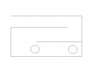
-My next thought concerned placement. I know that drivers are often placed part way down the line to smooth out the high frequency irregularities (not completely clear on the theory behind that yet) so the immediate question that comes to mind is what would happen if we placed one driver toward the beginning of the line and the other part way down the line as shown below? Anyone ever try that?
-Another possible variation is to place two drivers with different parameters in the same pipe. If drivers were chosen carefully might they possibly compliment each other making a system with a wider passband than is possible with either driver alone (in a non-stuffed line)? Thoughts?
mike
-Would you design a line for a single driver and then just double the area of the pipe?
-Or would you design a single pipe for an imaginary driver with twice the Sd and Vas?
-My next thought concerned placement. I know that drivers are often placed part way down the line to smooth out the high frequency irregularities (not completely clear on the theory behind that yet) so the immediate question that comes to mind is what would happen if we placed one driver toward the beginning of the line and the other part way down the line as shown below? Anyone ever try that?
-Another possible variation is to place two drivers with different parameters in the same pipe. If drivers were chosen carefully might they possibly compliment each other making a system with a wider passband than is possible with either driver alone (in a non-stuffed line)? Thoughts?
mike
Attachments
Hi,
There are a number of TL designs using two drivers to smooth response.
THe simplest is the Thor : http://seas.no/thor.htm
more complex the Ariel : http://www.nutshellhifi.com/Ariel.html
Exact cancellation of modes is difficult, smoothing easier.
") /sreten.
/sreten.
There are a number of TL designs using two drivers to smooth response.
THe simplest is the Thor : http://seas.no/thor.htm
more complex the Ariel : http://www.nutshellhifi.com/Ariel.html
Exact cancellation of modes is difficult, smoothing easier.
/sreten.take a look at Martin King's website -- he has written several white papers on the topic. http://www.quarter-wave.com/
Ap said:I would get the drivers as close together as possible - this way they will couple more effectively. Placement 1/3rd the way down the line is best for hf response. As for size just double Sd. If your calculations require Vas then double that as well.
and don't forget to manipulate Re as well.
Very good. Thanks for all the good tips. I was thinking allong the lines of a more extremem version of what the Thor does (but for sub only so sans tweeter and stuffing).
I will probably have to find a way to get Martin's stuff to work on my computer (or just learn the mathematical theory so that I can calculate this myself) since the software I have can not model driver location. If I could determine the locations that would attenuate the first and second irregularities I could then try placing a driver at each location and see what happens.
mike
I have heard that MJK's spreadsheets can do this task. I have seen and heard of people using this method (on the internet, not in person), but most of the time you see the drivers mounted close together at the end of the line. Supposedly they work magic on the harmonics and work good for low response as well, because they are located at the end of the line. Unfortunately, most of the info I have happened upon on this subject are on non-english webpages, so I don't know much.
As I reviewed Mr. King's web pages it appears that I may have misunderstood the effect of offset drivers. It appears that the 1/3 length placement affects all of the harmonics not just the first. If so then different locations for multiple drivers probably does little if any good.
What was not clear is how one adjusts the location in a tapered line so that the impedences of the closed and open lines work together for proper cancellation. I would guess that the driver would need to be less than a third of the way down in a tapered line.
mike
What was not clear is how one adjusts the location in a tapered line so that the impedences of the closed and open lines work together for proper cancellation. I would guess that the driver would need to be less than a third of the way down in a tapered line.
mike
- Status
- This old topic is closed. If you want to reopen this topic, contact a moderator using the "Report Post" button.
- Home
- Loudspeakers
- Subwoofers
- Multi driver TLs