that's pretty wild - driver at mouth - adjustable throat on hinge- leaky branch with holes - comparison to saxophone
OT -- like to figure out fairly smooth Karlson front chamber for 10" and 12" - what happened in that taller box you built for 8" fullrange? - did you cut the slot all the way up to relieve it from pressure buildups?
maybe a Karlson testbox should have baffle on hinge to get quick RTA (looking to avoid large nulls) although pipe's upper panel above baffle will have to move too. some cant of the upper panel might be favorable sonically as would be a reflector at top. less baffle tilt is supposed to decrease the so-called "reverb" but not always the case as far as hangups
Hi Guys
There is nothing conceptually new about putting a driver into a duct or folding that duct or having both sides of the driver in that duct.
The issue is how do you arrive at a set of conditions, which allow something like “flat” response without ringing.
Also, I had never seen the Jensen Transflex until a friend sent me a write up, I was initially bummed but then surmised why there were no products I knew of based on this approach.
The idea came from working on the Unity speakers and wondering “what if” I substituted the back side radiation from the driver for the reflected sound.
Anyway, the nub where the light went on was realizing that horns are fundamentality resonant devices like a pipe BUT the resistances compared to reactances set the “Q” of the resonances.
When a horn mouth is large enough, the resistances fully swamp the reactances, when its not large enough, there is a peak at the bottom, a broad dip and then another peak and a series of peaks closer together and decreasing magnitude (as the horn is acoustically large enough higher up to proved more resistance).
When the large dip is big enough, the horn is unusable and so this (how much dip) sets how small one can make a horn of a given cutoff.
Acoustic impedance, it is something like hydraulics, when you have a heavy driver with a strong motor, one wants a throat that is smaller than the radiator area (aka compression ratio). A light driver would require less compression ratio (all other things being equal).
This is one place the acoustic impedance can be juggled.
In this diagram, one can see the change in velocity and pressure in a quarter wave resonator. This also represents an impedance change although there is (for all practical purposes) no resistive component inside.
http://www.passdiy.com/projects/el-pipe-o-3.htm
It dawned on me that the reason one never saw the normal impedance rise on a high efficiency horn until about an octave above low cutoff was because the driver needed to be at a Velocity maximum to develop the motion / velocity..
All the horn driver design math is based on a full sized horn which is at least ½ wl long (with a constant resistance).
The quarter wave length mode is very different, it has a velocity minimum at the driver.
In reality, the driver has reactances in the form of its spring and mass reflected through as parallel inductance and capacitance in addition to the resistive portion set by the driver BL and Rdc.
So, the Tapped horn is a juggling of the changing resistances and reactances of a “too small” horn with those of the driver, by adjusting where along the horn one Taps the rear radiation, one adjusts a variable “area” effect. Now, in the range where the dip had been, one has constructive addition filling in that region by in effect only using one side of the radiator at the low cutoff and both sides where the dip would normally be.
It takes a driver suited to drive the motional minimum which would not be a good horn driver above that, however, by having both sides feel the radiation resistance above that, the driver in effect has a larger radiator and a more suitable acoustic impedance on the motor.
Anyway, when everything is right, the result is that for a given ripple and low cutoff, the horn can be made smaller.
GM, your down in the area of the shop as I recall, next time your out getting some of that good BBQ, give the shop a ring and stop by for a listen. They are starting to build a special walk in tapped horn which should be humorous. The customer wants 104dB from 15 to 20Hz at 250 Meters from the source and it has to run 24 / 7. Not really a home sized Tapped horn as it has 40, 16inch Drivers and 40 1Kw amplifiers in it.
Best
Tom Danley
Greets!
I'd love to! When you offered last time I wasn't up for any 'road' trips, but I'm walking ~upright again and finally got some 'wheels', so let me know when you're going to be down here and we'll make a long lunch of it if you have time.
Kool project! Wish I had a movie palace sized HT to put it in!
GM
The customer wants 104dB from 15 to 20Hz at 250 Meters from the source and it has to run 24 / 7. Not really a home sized Tapped horn as it has 40, 16inch Drivers and 40 1Kw amplifiers in it.
104dB @ 15Hz @ 250m 24/7. Hmm. The potential to vaguely nauseate all life within about a square kilometer. Normal quantitative superlatives fall a bit short.
 Sounds like you're into WMD design there (weapons of mass discomfort/disgorgment).
Hi Bill
Yeah, I’ll bet it’s not for playing disco music too but they won’t tell what it is for.
Some other folks were asking about something like this a few years ago but that was for testing some kind of sensor or something and I don’t know if these guys are on the same thing.
Since it is built into a shipping container, I suppose if they were looking for someone in a cave, they could park this coupled at the mouth and get sort of an “acoustic toilet plunger” effect.
Perhaps if they had good sensors, they could locate all the other openings via the acoustic radiation or something, I don’t know.
Best,
Tom
GM
Glad to hear your on your feet!!, didn’t know you were having problems.
I get down there every so often; I’ll let you know next time I going.
Meanwhile if you want, give em a call and say I suggested you call and ask for a demo.
Best,
Tom
Freddyi
You continue to be a source of patents and papers I have not seen, thanks!.
Boy that horn is weird, conceptually I see what he is after but any time I have had big leaks in horns it has not been a good thing.
As in saxophone of other resonant horns, only ONE leak is allowed at a time as the one closest to your mouth, dominates all the rest.
I wish I had more time to reply to your Karlson quest, I have looked at the response curves you posted a number of times and thought, I see some (not desirable) things related to length and width (notches due to standing waves), some things like an acoustic band bass and yet the generally rising response is more like an increasing acoustic loading like a horn.
I think he was onto something but he is only tickling “it”.
An exponential horn is already an adaptive resonator (at least that’s what I see as of now) that is damped by a significant and unchanging acoustic load, which lowers the Q to the point of invisibility so far as radiated pressure.
In some ways a horn is like a helmholtz resonator, in other ways it is not.
An acoustic filter in front of a driver is usually made of an air volume and mass, this would be like a front volume and port mass in a band pass speaker etc.
Helmholtz resonators are phase inverters, produce a 180 degree phase shift between the driving pressure and output pressure. A quarter wave resonator, the lowest mode of such a thing, only has a 90 degree phase shift I / O.
My impression / hunch at the moment is that the K coupler needs to be driven at one end, and has to be acoustically consistent with horn dimensions for “that” frequency.
My hunch would also be that the slot would not run the entire length of the horn but rather the small end would be at the point where the horns active length would be at the desired high cutoff.
In other words, for a quarter wave horn, at the low cutoff, the entire length is active.
An octave above the horn is ½ wl long and now it can become efficient.
Two octaves above the active length could be argued to be about ½ of what it is at the low cutoff etc.
The slot has to be small enough to not spoil the internal Q at the low cutoff and yet be large enough to acoustically establish that point as the “end” say 2 octaves up.
Sounds like ending up with some scrap plywood is involved.
Are you looking for something to go up to 300-400Hz?
Best,
Tom
Hi Tom - Moray dug most of those patents -haha-
re:Karlson = they look to cut cone excursion but can be hellish & bizzare sounding things. The original Karlson from 1951 to me is "about" liveable and sometimes fun. Cavities resonate at ~300 for old K8, 235 for K12, 225 for x15 and Acoustic Control's (Zintz's) 115BK, 155Hz for K15 and I've knocked it down to 135 or so - a coupled cavity peak doen't help matters.
dunno if any sense in doing a tall K with slit-slot but - maybe? should it have some positive flare? 300-400 is a good upper limit.
Best,
Freddy
ps - BP like tradeoff
http://img72.imageshack.us/img72/8470/6capzwtf4.jpg
http://img72.imageshack.us/img72/8075/20ltradeoffxy4.jpg
Freddy and Tom...
I like the look of that cabinet that Ken designed. In the ones that I built for a full range driver I made half (the first half) of the line zig zag back and forth from the driver up to the top of the Karlson coupler section. The idea was to eat up high and mid frequencies and stop/slow down/delay them from reaching the driver. The result was and is very good. The speaker sounds very good smooth with no noticable problems. The line has some 1/4 inch thick felt pads on the bends in the zig zag section but aside from that there is no other line damping at all. First attempts had lots of fiberglass stuffing but over time I removed it all to benefit.
Tom if you are interested in any other patents that I find I would be hapy to send them directly to you. I would be interested to know what your take on Ken's design is and what you might do to improve on it? Freddy is right about how Karlsons reduce the driver motion. They have an amazing ability to coulpe the driver to the air and the small one that I am running now (6 1/2 inch FE166E) has astounding sound stage qualities you really hear the recording venue overlap the listening room and with great recordings it can feel like you are in the venue not your own room. I took the 166e version of this speaker down to the Rocky Mountain Audio Fest in Denver three years ago (Freddy, Lee go to hear that one just before he passed away) and I got some very nice comments about it. I was told by one dealer that the only other speaker that could do stage and image in the same way was the Cogent that was there. Well enough horn blowing I just wanted to impress upon Tom that there is some serious potential here and that with Tom's ability to get inside of a concept the door just might get unlocked. JK would be happy to know that people cared enough about what he did to take it to the next level. Makes a nice connection with the past and moves it into the future. That's what it's all about I think. Regards moray James.
Hi guys -
-like to get a handle on regular-syle large Karlson's front pipe and aperture to lower its apparant lumped tuning around the 3rd impedance peak without increasing bulk over K15. I did it with a 6" high 20 liter right angle stub somewhat like KenL's idea of a year or two ago connected to front chamber on coupler with 2"x19.5" slot above the reflector. This stub moved the 3rd Z peak of the same coupler from ~190Hz down to around 120 or so. K15 has the peak ~155Hz. Dunno if this stub was good distortion-wise at high input powers as my try was in added pieces. 85L rear chamber was ok for an 18" with qts ~0.25 and mms 103g.
I may be barKing up the wrong tree with a simplistic view of coupled-cavity peak juggling but can't crunch the math needed to do analysis. One engineer may provide some aperture inductance formulae in a few months to be put into basic or whatever (?)
Karlson's 1951 K15 box (K15 went to NYC Audio Fair in October 1952) is a loud player with lots of outout in its range for low cone motion with driver type of its time - low mass - low inductance. FWIW I've measured worse distortion in some horn. Below cutoff the cone motions seem better controlled than a reflex of its rear chamber size and tuning.
I don't think theres any midband gain - there's potential for ripple, balance issues and "reverb"- ha- certain baffle angles may work better/different than others.
maybe Tom can look at Karlson for what it is (whatever mix that may be)
IIRC, KenL's tall k had a dip -maybe Ken can join the conversation.. A slot might not be good for tapped horn (?)
hey Tom - you musta heard k15s
Freddy
Tapped Horns (Back on topic)
To get this thread back on topic, I'd like to point you toward some measurements I've taken on some tapped horns I've built. Have a look at: http://diy.cowanaudio.com
Cheers
William Cowan
To get this thread back on topic, I'd like to point you toward some measurements I've taken on some tapped horns I've built. Have a look at: http://diy.cowanaudio.com
Cheers
William Cowan
William,
How did you go about choosing a suitable driver for the tapped horn design? Can you talk about this process? Was it just a trial an error? What do I look for in a driver? I'd like to make a giant one, aiming to be flat to around 15hz. I'd guess a 15" driver would be suitable. I realize that this wouldn't be a high bandwidth design, but I plan on integrating with smaller sealed subwoofers at around 40hz. I'm just trying to get the most flat output for the buck in that lower region.
How did you go about choosing a suitable driver for the tapped horn design? Can you talk about this process? Was it just a trial an error? What do I look for in a driver? I'd like to make a giant one, aiming to be flat to around 15hz. I'd guess a 15" driver would be suitable. I realize that this wouldn't be a high bandwidth design, but I plan on integrating with smaller sealed subwoofers at around 40hz. I'm just trying to get the most flat output for the buck in that lower region.
G'day Lindahl
Driver choice is not much better than trial and error. We still get some surprises, so I'm not happy to choose drivers for people.
Initially aim for a Qt of 0.2 to 0.4 and an FS near your LF cutoff. That should get you close. The drivers I've found work well have a low VAS.
With a 15Hz LF cutoff, you should be able to see 60Hz before the first dip. I use an 18Hz dual 830500 design that is pretty flat to 70Hz.
Hi William - my apologies on throwing the tread off (alhough in a sense, JK's K15 driver sat in its mouth)
its fascinating to see stories and poor plots on Jensen-stye transflex attempts online while a bit of tilt creating a positive flare gives beautiful plots on your speakers (when things are right).
if I feel better and can get plywood and B&D saw going down a guide then will give one a go. any hints on the 18 T-H? - would be cool with my theatre organ cd collection.
Cheers,
Freddy
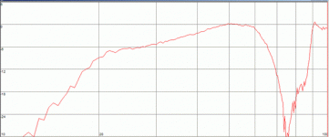
G'day Freddi
The 18Hz horn does work very well in room. Here is the near field response. In room it's pretty much flat. The rolloff above 60Hz requires a low crossover. I'll put some details on my webpage soon. It's BIG. It has the nick name "The Coffin" I think it's a bit big for that!
Cheers
William Cowan
The 18Hz horn does work very well in room. Here is the near field response. In room it's pretty much flat. The rolloff above 60Hz requires a low crossover. I'll put some details on my webpage soon. It's BIG. It has the nick name "The Coffin" I think it's a bit big for that!
Cheers
William Cowan
Attachments
Tom Danley said:GM, your down in the area of the shop as I recall, next time your out getting some of that good BBQ, give the shop a ring and stop by for a listen. They are starting to build a special walk in tapped horn which should be humorous. The customer wants 104dB from 15 to 20Hz at 250 Meters from the source and it has to run 24 / 7. Not really a home sized Tapped horn as it has 40, 16inch Drivers and 40 1Kw amplifiers in it.
Best
Tom Danley
A couple of weeks ago I was staying at the Aladdin during CES. They have an "indoor thunderstorm" in their shopping mall. The first thing you notice about their thunderstorm is that it sounds terribly anemic, because there's no low bass at all.
Something like that would be great for theme parks and hotels.
:: PB ::
- Status
- This old topic is closed. If you want to reopen this topic, contact a moderator using the "Report Post" button.
- Home
- Loudspeakers
- Subwoofers
- Tom Danley's TOWER OF POWER