Beauty is in the eye of the beholder. That design may not be beautiful, but I think it is interesting. Oh, and very effective.I thought of placing the pipes out of the box, but something like 2 meters of piping ? That wouldn't look very nice would it
... I've never seen a PR used for the front chamber of a 4th order bandpass ...
It's been done commercially. Creative Inspire Digital 5700 (scroll down for pictures):
Multimedia speaker comparison: Altec Lansing Select 4100, Cambridge SoundWorks FPS1600, Creative Inspire Digital 5700 and Logitech Z-560
(Scroll further down to the Logitech Z-560 review to see a heroic attempt to put a long port in a short box...)
Beauty is in the eye of the beholder. That design may not be beautiful, but I think it is interesting. Oh, and very effective.
Some examples:
Subwoofer Projects
PR
It's been done in PRO sound also. OHM TR sub use 18" pushed 21"(?) membrane. It works. And works very well.
It's been done commercially. Creative Inspire Digital 5700 (scroll down for pictures):
Multimedia speaker comparison: Altec Lansing Select 4100, Cambridge SoundWorks FPS1600, Creative Inspire Digital 5700 and Logitech Z-560
(Scroll further down to the Logitech Z-560 review to see a heroic attempt to put a long port in a short box...)
It's been done in PRO sound also. OHM TR sub use 18" pushed 21"(?) membrane. It works. And works very well.
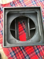
Attachments
It's been done in PRO sound also. OHM TR sub use 18" pushed 21"(?) membrane. It works. And works very well.
Which brand is it exactly please ?
that isnt a bandpass I believe from what you described. Its an alignment that doesnt have a common name. What you described was that the driver itself was in a bass reflex box which was vented into two boxes, one on either side, which then had passive radiators to radiate into space. That is exactly the same idea I had once. Good luck on designing the box with a predicted FR though!
This is the sort of problem that is easy to model in AkAbak. Get me the volumes, port lengths and TS params for both the driver and PR's to start and I will see what I can throw together.

I've long wondered if someone could use a flexible cabinet wall instead of a passive radiator.
IE, the efficiency of a passive radiator is correlated with it's size. So why not use the entire wall?
It wouldn't be practical for a commercial design because you'd have to literally tweak the weight of the wall, but for a DIY design it might be worth the trouble.
IE, the efficiency of a passive radiator is correlated with it's size. So why not use the entire wall?
It wouldn't be practical for a commercial design because you'd have to literally tweak the weight of the wall, but for a DIY design it might be worth the trouble.
I've long wondered if someone could use a flexible cabinet wall instead of a passive radiator.
Hi,
B&W built something along those lines. A rectangular wall / driver
hinged along one long side, and a surround for the other 3 sides.
rgds, sreten.
...the efficiency of a passive radiator is correlated with it's size.
Really? In what way?
Really? In what way?
Think of it as how the movement is coupled to the air.
More linear movement normally goes with allot of deformation of material witch is converted in heat. So you don't recover all the energy from the movement in a spring like fashion. a larger surface area witch less linear movement should move more air more efficiently.
There should be a x^2 calculation in there somewhere, but is has been a while.
Same rules as a larger diameter speaker.
There is some misinformation in this thread. When using a PR for a 4th order bandpass exit, you don't want to tune below the bandwidth of the design. A bandpass in essence uses the tuning point of the PR (or even port) as the relative midpoint of the bandwidth of use. The sealed and vented chambers to either side of the active driver then are also used to adjust the F3 points of the design. The Fb/tuning does work with the rolloff of the vented side. If you tune below the point of bandwidth required, you'll effectively have a few hertz of operational bandwidth instead of the broad 30-40 Hz or larger difference between cutoffs that is usually preferred. The bandwidth will loosely 'follow' the tuning of either the PR/port in that if you shift the Fb lower, the bandwidth will be a lower freq range, and the range will be higher if the Fb is higher. I don't mean the span or bandwidth of the range, as you could look at it like a shifting raft on a lake. Lower Fb moves raft (bandwidth) to left and vice versa. Of course this is all relative to the type of alignment desired, but the raft will still work similarly. For the most part, the tuning is near the upper end of the range the system will operate.
As an example, in my "Overdrive 10" design also posted here at DIYaudio recently, I have a tuning Fb of 50Hz for the PR, yielding F3 points of roughly 30Hz to 60Hz without the amplifier boost coming into play. As a reference note, my volumes are 18 ltrs sealed, and 8 ltrs for the PR.
Some other things involved here are the volume of the front chamber usually has to be very small to raise the tuning of the PR from the get go. Since most are typically a higher mass PR design meant for average PR box designs, their relative tuning is fairly low in your average box size. Then both the PR and the active driver have to occupy this front volume, so shape and dimension come into play to keep them from contacting each other during use. Typically, if the surround is more than an inch from the PR frame/basket, then you have enough room. The PR rearward motion is only related to the mass, the nut/bolt length, or the (sans, of course) voice coil former. The driver motion is mostly in the middle from the cone, and is typically set further from the surround. If the driver has less than 50mm of (p-p)Xmax, it will not breach the surround's most-forward point. Same goes for the PR- it would need to have more than 50mm Xmax to contact the active driver with the same spec just stated. More notes- My PR 8 ltr sector is only 4" deep to accommodate the 12" PR and net the volume. Just to be safe, I mounted the sub recessed into a 1.5" baffle to avoid contact.
It really takes a driver with special characteristics to work in a design such as this, and boost is usually a requirement to get low enough with the tuning Fb requirements for bandwidth, and I would recommend the 10" active/12" PR arrangement so the woofer can mount through the PR hole.
More info- James Loudspeaker makes a pro version of a PR-bandpass as well, using a driver and PR of the same size.
Best regards,
olf
- Status
- This old topic is closed. If you want to reopen this topic, contact a moderator using the "Report Post" button.
- Home
- Loudspeakers
- Subwoofers
- Use passive radiator in a bandpass?