Hi Art,
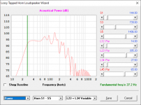
Below you see an example of the modeling of the CS30. I just a very basic script, without some fance input parameters, based on lumped elements.
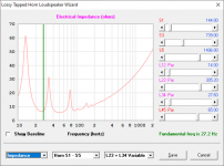
I have to correct some earlier post. By underdamped i mean a relative big enclosure that`s normale not used to give the driver the traditional flat response. The LAB12, danley model, is a very strong driver that gives you a very small enclosure with a big low tuned, unpratical, port to make it flat. The bandpass enclosure is not efficiency reasing but more a high sensivity system.
Giving the driver a somewhat bigger enclosure with a port that is tuned higher than normal gives you the big peak at the low cutoff. Placing a inductor in series with the driver give a second big peak about an 1/2 ocatave higher.
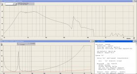
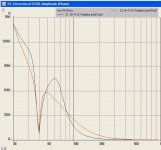
In that attachment you see a very (rough) similair response with of the CS30. I have plotted the impedance response to the total systeem and a plot of the netwerk impedance between the coil and driver. Its giving the same similarities.
Please don`t look at the absolute values, because the modeling script isn`t been build (and tested) by me.
The same set-up could be made with the normal version of eminence, but you need to reconfige the enclosure/port, because the driver is not as strong as the Danley version.
The danley studio subwoofer uses the same bandpass configure. Here you notice the normal impedance plot on the danley website. PS: do you maybe know what driver is been used by Danley?
Hi Kyle,
I have seen and listen the video of the CS30 (table version) on the YT channel. Listen with some good headphone, you immediately know it sounds huge!!
PS: interesting about a second chamber. Wasn`t aware about this and would like to find more about this. Indeed the port has some kind of structure that avoids port noise.
Below you see an example of the modeling of the CS30. I just a very basic script, without some fance input parameters, based on lumped elements.
I have to correct some earlier post. By underdamped i mean a relative big enclosure that`s normale not used to give the driver the traditional flat response. The LAB12, danley model, is a very strong driver that gives you a very small enclosure with a big low tuned, unpratical, port to make it flat. The bandpass enclosure is not efficiency reasing but more a high sensivity system.
Giving the driver a somewhat bigger enclosure with a port that is tuned higher than normal gives you the big peak at the low cutoff. Placing a inductor in series with the driver give a second big peak about an 1/2 ocatave higher.
In that attachment you see a very (rough) similair response with of the CS30. I have plotted the impedance response to the total systeem and a plot of the netwerk impedance between the coil and driver. Its giving the same similarities.
Please don`t look at the absolute values, because the modeling script isn`t been build (and tested) by me.
The same set-up could be made with the normal version of eminence, but you need to reconfige the enclosure/port, because the driver is not as strong as the Danley version.
The danley studio subwoofer uses the same bandpass configure. Here you notice the normal impedance plot on the danley website. PS: do you maybe know what driver is been used by Danley?
Hi Kyle,
I have seen and listen the video of the CS30 (table version) on the YT channel. Listen with some good headphone, you immediately know it sounds huge!!
PS: interesting about a second chamber. Wasn`t aware about this and would like to find more about this. Indeed the port has some kind of structure that avoids port noise.
Attachments
Last edited:
Kyleneuron,It’s not strictly a bass reflex as I see it. The porting has a constriction, and there's an additional 'chamber' which you can't really see from that angle on these old wireframe drawings.
Also, while I'm all for learning and digging into things that are interesting, I wasn't aware that it's cool to post the internals of current commercial products here?
DSL’s website currently shows the loading
The wire frames for many of the DSL enclosures were posted on their website for a short period of time in 2012, and downloaded by many in DIY community who were quite interested in the cabinet designs. Although I don’t generally re-post them, this particular discussion led me to, as the driver you and Marcel suggested (which seemed the logical choice), looks very different from the one depicted in the TH112 wire frame, but the same as the one in the
Although the LAB12 and the DSL12 look nearly identical, the difference in voice coil diameter (2.5” compared to 3”) and inductance are significant, a Le of 1.48mH compared to 5.08mH, the upper response will be quite different in any type of enclosure. Although Marcel’s suggestion of a
Ports with “constrictions” have been around a long time, BIC patented them as “venturi ports” in 1973. DSL literature calls it “a specially designed port”.
Ports generally shaped like the CS30’s were well documented in the white paper by Alex Salvatti, Doug Button, and Alan Devantier’s “Maximizing Performance from Loudspeaker Ports," presented at the 105th AES Convention in September 1998.
Are you suggesting the approximately 5 inch vertical bracing at the narrow point of the port and in a similar place on the top of the CS30 is “an additional chamber”, or are you aware of something different in the cabinet design?
Art
Marcel,Giving the driver a somewhat bigger enclosure with a port that is tuned higher than normal gives you the big peak at the low cutoff. Placing a inductor in series with the driver give a second big peak about an 1/2 ocatave higher.
In that attachment you see a very (rough) similair response with of the CS30. I have plotted the impedance response to the total systeem and a plot of the netwerk impedance between the coil and driver. Its giving the same similarities.
The danley studio subwoofer uses the same bandpass configure. Here you notice the normal impedance plot on the danley website. PS: do you maybe know what driver is been used by Danley?
I was not aware of the dual 8” DSL “Studio Sub” until you mentioned it, don’t know what drivers it uses.
If I’m getting what you say correctly, the simulation you posted using a 11mH coil in series with the driver drops the impedance minima from 44Hz, (normal for a 44Hz Fb) to around 38Hz, while providing a larger than usual frequency response peak around and above Fb. Sounds like a description of the CS30’s response, though it does not roll off so steeply below Fb as the simulation.
The dual 8” DSL “Studio Sub” does have a similar frequency response to the CS30, though it’s impedance response is similar to a high Le ported woofer.
My guess is it’s reduced upper response is DSL’s market speak for “a new form of acoustic bandpass” . It’s phase response had me going- the last digit is cut off below 90 degrees, “-360” appears as “-35” ;^).
Phase response over the band-pass of the CS30 and Studio Sub seem similar to a ported cabinet with similar Fb.
I thought your suggestion that an inductor is used on the CS30 might account for it’s flattish impedance response, but it appears to be just another DSL data sheet error.
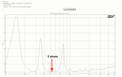
The IEC standard (IEC60268-3) allows any impedance above the rated value, but limits the impedance below. It does not allow the rated impedance to fall below the 80% of the nominal value at any frequency.
Though DSL corrected several models spec sheets to reflect that standard (after I brought it up with Ivan Beaver) they still have not corrected the nominal impedance on the CS30 or TH112, which both have impedance minima near 5 ohms.
Art
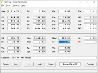
Here are the parameters of the beefed up version of the danley lab12
Data-Bass: Subwoofer Measurements
That could explain the relative low -3db response of the TH112. The place of the driver is within the horn to compensate the "saddle" between the horn 2 highest hornloaded points, around 60hz.
More likely it's to compensate for a hump rather than a saddle in the passband response. The DSL version of the LAB 12 has a pretty high inductance and, based on a bit of experimentation with a Honresp sim, increasing the distance between the driver and the mouth can reduce that hump quite a bit.
What the offset between the driver and the mouth does NOT do is change Fb at all, which makes me wonder why this would be considered a better solution compared to just using a low inductance driver (which is usually found in better motors) in a smaller box (because it requires no such offset) that would achieve the same Fb.
BTW, I tried modelling the DSL 12 in a TH of similar size with the driver offset from the mouth. While the passband looked similar, the SPL at 2.83V was not 100 Hz. It was closer to 95 Hz. And while the frequency response did look "usable" up to 200 Hz, the GD above 60 Hz is concerning. I was going to put together a BOXPLAN to allow modelling of different drivers in a similar offset-driver arrangement, but I might delay that now because I can't really see the advantage of doing so.
Last edited:
What the offset between the driver and the mouth does NOT do is change Fb at all, which makes me wonder why this would be considered a better solution compared to just using a low inductance driver (which is usually found in better motors) in a smaller box (because it requires no such offset) that would achieve the same Fb.
Its the total horn lenghtm from throat to mouth, what provides the acoustic impedance to the driver and sets the -3db point.
I wouldn`t look to much to the high horn resonance`s in the modelling programm. Its been written by Tom that the most modeling software do tend to model these with too much reactance loading effects.
It is the low frequency response of the TH112 that i find very strange and can`t track this back with an basic script in akabak.
If I’m getting what you say correctly, the simulation you posted using a 11mH coil in series with the driver drops the impedance minima from 44Hz, (normal for a 44Hz Fb) to around 38Hz
Indeed this is also a side effect of the coil and having a relative shorter port sets the unwanted port resonances a little higher. If you look to the excursion plot you also notice u much lower excursion at the passband.
gr. Marcel
Marcel,
Additional excursion with the same voltage applied would increase sensitivity, but without seeing with and without the series inductor and the frequency, impedance and excursion response, the information still is not complete.
Also would be interesting to see the voltage required to hit 15mm excursion above Fb.
Its the total horn lenghtm from throat to mouth, what provides the acoustic impedance to the driver and sets the -3db point.
I wouldn`t look to much to the high horn resonance`s in the modelling programm. Its been written by Tom that the most modeling software do tend to model these with too much reactance loading effects.
It is the low frequency response of the TH112 that i find very strange and can`t track this back with an basic script in akabak. [/quote[
I was able to get something pretty close to the published FR and impedance curve of the TH112 by taking the published external dimensions, calculating the volume, subtracting about 20%, and then using Hornresp to come up with a TH of similar layout (longer than expected L45 segment) and similar impedance curve (peaks and dips in approximately the same locations). The Fb is definitely set by the distance of the driver from the throat, not the complete length of the horn. The behaviour at and above Fb is set by the expansion along the path, and I was able to approximate that by using a small S1 as indicated by the line diagram of the TH112's internals. Adding some figures for segment stuffing / lining in the Hornresp sim gets the FR even closer to the published spec.
The only issue is that the overall sensitivity of the sim does not match the published sensitivity. It's off by 5dB.
I was going to do a BOXPLAN for the TH112 layout to fine-tune the sim a bit further but, like in the case of the TH-SPUD, I'm not sure that I see any gain in doing so. Taking the same driver, using it in a more "traditional" TH of less volume with less compression at S1 seems to produce a better passband FR in the Hornresp sim, at least in my eyes.
The Fb is definitely set by the distance of the driver from the throat, not the complete length of the horn.
If not there is no possibility to reach the 27hz horn loading of the TH112. (See the null in the impedance plot from danley`s). It looks like to me the distance from the throat to the driver back side is to short for this. The total horn resonate at a quarter wavelenght.
I am curious if you are able to model the falling frequency response from 38hz to 27hz according the danley specs. At 27hz you see soft knee where acoustic loading stops. At first sight i would think this is a non lineair kind of response like a restricted air flow from a to small portion in the horn, but i am not sure. I had once modeled the TH (lab12) from Don Snijder and that simulation plot did gave me similair results as his measurements in the low cutt off area.
Also would be interesting to see the voltage required to hit 15mm excursion above Fb.
You could multiply this from the previous excursion plot as there there are not none lineair lumped elements in the model. PS: I wouldn`t rely too much on these models as exact data.
Last edited:
Oh dear, I see what was happening. When I changed L45 in my model, Hornresp was happily adding the change to L34 to keep the path length the same, sigh.
The behaviour around the cutoff frequency is influenced by the compression at S2.
This is the model I came up with, based purely on driver parameters, external box size and the impedance curve. It probably needs to be adjust a bit to make it a more accurate representation of the TH112 fold.
The behaviour around the cutoff frequency is influenced by the compression at S2.
This is the model I came up with, based purely on driver parameters, external box size and the impedance curve. It probably needs to be adjust a bit to make it a more accurate representation of the TH112 fold.
Attachments

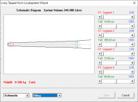
Brian,The behaviour at and above Fb is set by the expansion along the path, and I was able to approximate that by using a small S1 as indicated by the line diagram of the TH112's internals.
The only issue is that the overall sensitivity of the sim does not match the published sensitivity. It's off by 5dB.
DSL used two different frequency response measurements in the spec sheets for the TH-112, the 3/4/05 is 3dB less sensitive than the 8/11/05.
The upper two frequency response peaks in the 3/4/05 match the 3/4/05 impedance peaks, the "more sensitive" 8/11/05 upper peaks do not.
Both spec sheets use the same impedance chart, though it is unlikely that the more sensitive cabinet has the same impedance response as the less sensitive unit. Both spec sheets
The impedance drops to 5 ohms (both spec sheets claim 5.3 ohm 53 Hz minima, chart looks like 5 ohms), so 20 volts (4 ohm standard) or 22.3 volts rather than 28.3 volts would be more appropriate for a "1W/1M" sensitivity rating.
The later spec sheet indicates cabinet weight has increased by 8 pounds (3.6 kilograms), similar to the weight difference between a driver like the B&C 12PZ32 and the DSL-12.
Art
Attachments
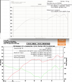
If i see it correctly i see the tef freq. response measurent
uses 2 different frequency resolutions 3.5hz vs 7.5hz. This explains the smoothed response. In the old plot the lowest 27hz knee cant be reconized.
But i can't exclude there are also other factors
that plays in here.
gr. marcel
uses 2 different frequency resolutions 3.5hz vs 7.5hz. This explains the smoothed response. In the old plot the lowest 27hz knee cant be reconized.
But i can't exclude there are also other factors
that plays in here.
gr. marcel
Last edited:
This is the model I came up with, based purely on driver parameters, external box size and the impedance curve. It probably needs to be adjust a bit to make it a more accurate representation of the TH112 fold.
The frequency response of your model if very close to danley`s measurement specs. Do you know what acoustic component horn response is adding when fill the horn with a quantity of damping (polyfill for instance)?
gr. Marcel
- Home
- Loudspeakers
- Subwoofers
- Danley TH-112 driver?