OPA2134 will be fine.
So this needs a 5V DC supply I guess based upon a quick look at the spec sheet?
So Pin 7 +5V and Pin 4 to 0V ?
https://www.ti.com/lit/ds/symlink/o...=https%3A%2F%2Fwww.ti.com%2Fproduct%2FOPA2134
Are there any easy mounting boards for the op amp anywhere - this is new to me!
A symmetric supply of +-12 or +-15 V is easiest to start with. +-12 V means -12 V, ground, +12 V. Operating opamps on a single supply is possible but adds more challenges. Connect a 100 nF ceramic cap between positive and negative rails, as close as possible to the opamp.So this needs a 5V DC supply I guess based upon a quick look at the spec sheet?
Last edited:
OPA2134 will be fine.
Yes something like that. The 7812 / 7912 work best with additional capacitors.
Thanks so much !
after or before the 7812
The room is 5.39m wide, 5.58m deep, and 2.95m tall and if you estimate the room mode in REW simulation it's pretty much at just over 31Hz ?
Near square rooms are of course worse for room modes.
OK, never heard a worse set of dimensions and Klipsch matching resonance. Hope you have no concrete walls or floor (instead of dry-wall that absorbs a lot).
But still, the FR doesn't look like rooms/speakers I've tested.
Try de-tuning the Klipsch (remove back?), other mic locations, and/or temporary acoustic tricks.
B.
")
Great -
Which one did you build? A, B or C
I don't suppose there is a way of also adding an active boost filter to lift the very low frequencies as well?
I may not need this but supposedly flat down to 20 Hz would be nice?
Great!
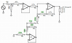
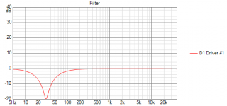
A quick and dirty gyrator with component values done with VituixCad.
The values have been Fo= 31.8 Q= 5.0 Peak=+20dB
If you post the REW unequalized measurement file, some further optimization may be done.
Hope this helps.
Eelco
The values have been Fo= 31.8 Q= 5.0 Peak=+20dB
If you post the REW unequalized measurement file, some further optimization may be done.
Hope this helps.
Eelco
Attachments
A quick and dirty gyrator with component values done with VituixCad.
The values have been Fo= 31.8 Q= 5.0 Peak=+20dB
If you post the REW unequalized measurement file, some further optimization may be done.
Hope this helps.
Eelco
Thanks for this - guess this is an alternative to the other active circuit?
Anything goes circuitwise, but I am afraid I have lost you (or vice versa..).
For starters: could you post the uncorrected REW measurement file? If that file can be used as a basis for the sims, basically any analogue filter with a Q until 20 and no more than a 20 dB dip can be generated.
What exactly is your target?
For starters: could you post the uncorrected REW measurement file? If that file can be used as a basis for the sims, basically any analogue filter with a Q until 20 and no more than a 20 dB dip can be generated.
What exactly is your target?
Hi, stepping in as I took the measurements and my brother (Tonescout) will be getting a suitable mic shortly to take his own recordings
As the sub is working in parallel with the speakers it will be understanding how the cut on the sub works with the mains to combine successfully, I wasn't able to measure the subs only as he was driving from the high gain outputs (power amp). It will require work with a digital solution initially to see what is needed then build the analogue version I suspect
In essence the cut will depend on the sub adding very little to the room node as nothing to control the mains (EQ)
Here are the measurements of the mains only across the seating area and averaged I have added the measurements with the sub working in the MLP sub turned on (green)
I have yet to look at phase, doesn't look too bad but I note that around 115 Hz the mains and sub are working against each other, so he will be needing to cut off the sub sooner beyond 80/90 Hz
The overly aggressive roll off at higher frequencies is being investigated
Attachments
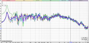
Is it my imagination or does your plot show just one location with astonishing 30 Hz peak and all the other curves nothing nearly so bad?
Not bad to have some bit of rumbling if it is down low - say below 40 Hz. But this room seems to show a rather bad hole just north of 30 Hz.... which can't sound good. Nor can just sucking power out narrowly at 30 Hz result in anything like satisfactory bass - even if it has superficial initial appeal.
For the moment, really a need for closer examination of speakers, locations, etc. Always great to have or borrow a Behringer DSP (its cheap) and try dialling-in various options, if only for testing (not sure why you'd ever take it out of your system). I am not optimistic about that room (esp if there are concrete floor or walls).
B.
Last edited:
B, hi
The green and significant peak is the subwoofer with the mains. all the others are just the mains. Yes the 31 Hz peak is the room node due to the relatively equal width and length and energised by both mains and subs. Looking at the REW sim, not a great deal placement can do to improve significantly
A
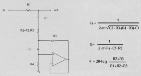
Looking at the calculator I have made - the 20% tolerance on the capacitors means I will have to select from samples to get the Fs correct.
My DMM seems incapable or broken when attempting to measure capacitance, so I just need to invest in a better model - can this be usefully measured with a DMM?
Thanks
My DMM seems incapable or broken when attempting to measure capacitance, so I just need to invest in a better model - can this be usefully measured with a DMM?
Thanks
- Home
- Loudspeakers
- Subwoofers
- Notch Filters to remove room modes