
GM,With such limited info, can't imagine this having any SQ anywhere near its 45 mm Xmax; Danley did it right using a synchronous motor/belt drive in his dual woofer/PR 14 Hz ServoDrive Contrabass subwoofer.
Most of the LF output of the SDL Contrabass came from the dual 18" passive radiators it used, each having 19mm Xmax.
The SDL Contrabass dual 15" had 9.5mm Xmax, impressive for the 1980's, but small in comparison to fairly commonplace subwoofers now.
If a rotary motor with belt drive were the only "right" or best way to provide linear excursion for a reasonable cost, Tom would have continued using the technology.
After standard moving coil transducers exceeded the SDL Xmax, and servo motors became more difficult and expensive to source, the approach was abandoned.
That said, the Contrabass output per size and power input still do not appear to have been improved upon.
Dayton Audio Ultimax18. Given 60 volts by the Dayton sa1000 amplifier?
1200 cm2 then 1200cm2 and then 400cm2, as 3 segments (two 180 degree immediate turns on centerline)
Driver at 0.349 offset in the split of the first fold, also the first fold location on acoustical centerline for air mass accumulatively as pressure node vs antinodes.
So it is as follows: 165.0cm ,155.0, 140.0cm. —> and 20.0cm after( tapped horn sim with L45 as 20cm).. that S4-s5 actual ‘area’, as 1200cm2 +,1200 cm2, plus 400cm2(no wood included) is 2800cm2. As its the far side of the cone. A rear chamber, But also centered as it can only fit and be perfectly simmed?
Impedance null at 12.4 hz, 90 degrees in phase is 26.8 hz(im in Wizard looking) , 7hz is the antinode in pressure ~120-140 hz is occuppied by both thd first fold and the last (as pressure (in length) is catching up to the sum as a wave form and harmonics.
Meanwhile stuffing was added and the first (L12 ) pipe at 3.349 kg and .23334 in segment number two(L23) and 1.2333 in L34. Noting the excursion never ever exceeds Xdamage through <10 hz in any amount of stuffing or varieties that still keep dB >100 at 10 hz and thus hypothetically a serious threat to 7.2 hz(sound as a weapon).
I ordered another Ultimax a few days ago and it arrives today.
What do you think? And,
Even then, we can confirm it in ‘PH1’ mode now, soon to be stuffed in next update as well? add an actual rear wall in phase from the point already established to enforce this ‘back wave’ we call ‘tapped’ entry and ensure its aware of itself or defining the ‘end of a wave verses a pipe? Whatever that means(?)
Attachments
Last edited:
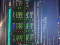
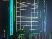
I then move to PH mode. Ive made a 50cm rear chamber. And i no longer use stuffing... 12.8hz. I stuff the front and ‘mid’ pipe as before then its 11.2 hz. As impedance nulls in wizard, 103dB at 10hz showing, no way Xdamage is ever a threat now unless i put 6 hz in this somehow? Its all clear as it is at 10 when the plot ends before DC...? Phase is beautiful. 25 hz is the first time warp and 180/-180 is at 80 hz, 150 hz is a cycle to the moon, 200 back in orbit, 300 and i splashdown in the pacific but it was a weird reentry!?!? The eagle has LANDED?
The ups man better hurry. I need to go find more plywood, home depots out and real russian birch layers is 65 miles away in traffic to east of N san fransisco bay... eek.
Ive run out and have nothing in the 13 ply Furniture grade pine/poplar blend left Who wants a new ULTimax 15. Maybe ill do this with car audio cabin to join in? How retarded would that be!?!
Im going for another 18 instead if this sim is what it is.. and i have no doubts its somehow tainted with a lack of reality. But where at?
The ups man better hurry. I need to go find more plywood, home depots out and real russian birch layers is 65 miles away in traffic to east of N san fransisco bay... eek.
Ive run out and have nothing in the 13 ply Furniture grade pine/poplar blend left
Who wants a new ULTimax 15. Maybe ill do this with car audio cabin to join in? How retarded would that be!?!Im going for another 18 instead if this sim is what it is.. and i have no doubts its somehow tainted with a lack of reality. But where at?
Attachments
Last edited:
No! Guys, sorry, i know you wouldnt call me a retard , it is however a result of typing and not anyones fault
Here:
GMs approach to the bose wave cannon with DJM(rip) is also a shape you can create in a paraflex type C. While that might not seem like anything or if doesnt (?) it might not be.. but it is if it is and the same idea is in an od qw pipe from another location(upstream).
But start adding more driver so they spread as 3 would in the space of 3 in the width of 120cm. Then use That if you want to or dont. It only represents things if you want it to. Only 10 or 12” drivers fit. I use two or an 18 allone(it doesnt matter, its flooding the area of offset in one side. If an imaginery middle.
Thats all only going to make sense if you build it. Wjateveryou do look ata PH sim as if its 240 and 80 cm. Then offset in that in ways you can and will if youhave to use only 20/40 or 60 cm from a closed end. The driver might even force it actually... 20 as 12 is 36? And 40 and its 2 12s....side by side and 60 as its then 3 centered at 60...
Thats pressure phase and itll show you 160/80, 80 or 120/120.....80 itll even show you 120/120/100 and 20. (Plus offset as you must now use it on both sides) If not. Youre csa in pipe chunks is wrong. Or, your offset driver position sucks. The driver ts parameters suck. Youre idea sucks. But one of those sucks, not physics..
. its there anytime you wanna see it. But if you dont make it possible you wont even be able to sim it. It never sucks when phase is represented from both sides.
PH mode is a clear perfect visual to what wasnt before it existed. All that remains is Q losses and friction to heat. The perfect path is now known
Its not an algorythm its reality. Ignore it or flare it? Its only phase if you look at it straight in the face as a pipe through a pipe.
14.5hz all day in a sim. But its not just that. Itll be lower... pressure phase and distance thru a folded pipe are not the same. One has actually hit a wall to exist. The other is a bunch of ideas snd advanced centerline didnt help pressure phase? It cant... so why try?
Fb is more important? Sure. But this is not qw. This is pipe physics. Qw is what were using i suppose, but its gotta be shoved through a pipe and its folded. Period. Nothing can change that except of you ignore it. We have been, and i think we forgot?
I dont know much. But i dont have to. I really on other peoples ideas. Theres something in a pipe. Its pretty much obvious if its 3 pipes. And offset driver entry is weird??? Look at it. What is there? Look at it as 3 pipes. But theres a 4th its whatever is at the exit of those that meet in sound not length. So make known. ‘Path’ is not knowing...’TH’ and ‘PH’ have no ‘path’. Thats important. It really is
This: while abbreviated in many ways it still represents something at the harmonic of something the long one as a qw to the shared full wave they both define or represent parts of...
The green only depicts the length so its obvious what it is or that it needs to be in order to be ‘perfect’ . Its all very easy to confuse in a corner. Lets try not to comfuse anything, lets assume we are all wise and our collective wisdom will figure out some thing we all might find very intersting and mutually fun?
‘Perfect’ is the question? What is ‘perfect’ and we are going to assume the csa anywhere (as pipe segments shown ) at a turn or end and overall lengths are fair to Fs and Vas. As well as not put out of wack with any Qes/Qms(Qts) that might skew our Fb /Fs too extremes not inherint of the design (type C paraflex with 1, 2 or even 3 12” drivers and s2 as needed (on or two or three radius, 20,40,60cm assume) that then defines 40 cm everywhere(skip corners or skip trying to, i dont think i can feed any thing but optomism here. And the entire idea of a dual pipe attached at the end needs to help in doubt. I won't even waste a moment there. Ill keep building them and pretend i dont know anything? Its kinda hsrd after aWhile. The answer is ‘nobody cares how it works’, that voodoo is lucrative. And DIY is free love.
What do see? What do you think? What makes sense?
This shows how i have drawn it in a way that jumps ahead of itself by the same margin so its not confusing anything as a big single quarter of a wave shape (sine)on the main long path and its turns, yet needs to be flat and thrn just one swoosh of 4 it represents....
Just perused these replies at the free-time I got, wish you were nearby so that I'd learn some acoustics.
Back to the topic, "paraflex type-C" you described seems to be a simple build, I'd like it too, but does it really dig deep, Googled and it shows the typical "paraflex type-C" at most is tuned at 35hz, but I need to go deeper down to 20hz, can it?
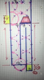
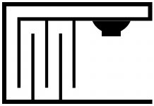
I remember btw you've stated "HORN is a silly thought of a PIPE dream", then answer me now, below are a HORN and a PIPE, but design is the same, so which is the better (or you'd agree to)...???
Attachments
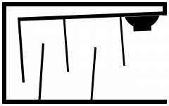

A horn doesnt exist. An expanding shape toward exit is not an impedance match until its entirely different looking and the mouth at those hz would be as big as the front if my house?
Silly words, but never the less, the pipe is entertaining realistic physics thats tight inside as soon as you put the pipe around the right part of a waveform thats parts fit in it, and/or after it in the pics . My drawings suck, but theres still a ckear picture of the idea and whats ‘needed’ in mist of them, even if outta scake?
Silly words, but never the less, the pipe is entertaining realistic physics thats tight inside as soon as you put the pipe around the right part of a waveform thats parts fit in it, and/or after it in the pics . My drawings suck, but theres still a ckear picture of the idea and whats ‘needed’ in mist of them, even if outta scake?
Attachments
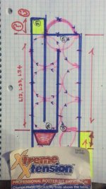
Just need lengths to get the right sum of phase vectors at the point they meet. If using pipe, you can use the pipe nodes and antinodes of a similar ((totally related in everyway thanks to harmonics or any length chosen in portions of as w model/sketch ) but its a smaller wave to show it or the cousin of it 3x as big or small.
That tends to be the same groupings in these things. Amd in reality you get multiples of 40/80/120/160 often (cm in a sim of parts). You might not know it, it might not be a straight pipe shape, but the paraflex holds this bd offset positions 100% everytime. The 2x 12 ‘cram’ type C, for example 40,120,80 and also 80cm on the other side of the driver. Thats all gotta dum at the imaginery point thats real. Draw it. iys a sine wave, so make it easy circles instead..
It work every time. In fact the last plain old qw pipe i just did for an rs265ho4 is ridiculously ‘perfect’ it seems, for what it is? I bought 3 more to try an ‘array pipe of sort or to spread 3 of a kind in a room with a 4th with identical geomtry in the ‘pipe’ ? No promises, only ideas. But talk isnt saw dust . And talk is con fusing. (Typing)... a paraflex is one thing. But its not the only thing yiu can do with the same idea. (Pipes, ones that coexist).
Attachments
Last edited:
Youre totally right, the ‘paraflex’ wont go low. But nobody asked it to. Its just a couple pipes and a driver. its not a ‘ Paraflex’. Nothing is, everything is ‘physics’?
Im down to 10.2 hz in the ‘pair of pipes’ that uses the PH sim or TH.. and an 18” ultimax. moved the pipes around. Just to describe offset.... its not a ‘pair of flex.’ Words suck, typings worse... But you make good ideas, just find the driver to use them in!! Itll be whatever you want it to be
Im down to 10.2 hz in the ‘pair of pipes’ that uses the PH sim or TH.. and an 18” ultimax. moved the pipes around. Just to describe offset.... its not a ‘pair of flex.’
Words suck, typings worse... But you make good ideas, just find the driver to use them in!! Itll be whatever you want it to be
Last edited:
I remember I've agreed before in a reply to what you emphasize about horn-folding, impedance at the little mouth of a folded-horn matching that of air seems mythical, yeah, but here's my question, what do you think then Mr. Tom Danley (read his ventures like the LAB-12 & the DTS 10/20) has been doing with horns for over two decades now inspiring many DIYers, I don't get this, just curious to know???A horn doesnt exist. An expanding shape toward exit is not an impedance match until its entirely different looking and the mouth at those hz would be as big as the front if my house?

Okay, if your drawings suck my drawings should be born suckers then, but as a "pipe smoker" in your own words, why won't you draw something for me in the meantime, I'm glad if you?Silly words, but never the less, the pipe is entertaining realistic physics thats tight inside as soon as you put the pipe around the right part of a waveform thats parts fit in it, and/or after it in the pics . My drawings suck, but theres still a ckear picture of the idea and whats ‘needed’ in mist of them, even if outta scake?
Yeah, we can talk, and that's what we've been doing to now, and still, confusing, but we should talk...Just need lengths to get the right sum of phase vectors at the point they meet. If using pipe, you can use the pipe nodes and antinodes of a similar ((totally related in everyway thanks to harmonics or any length chosen in portions of as w model/sketch ) but its a smaller wave to show it or the cousin of it 3x as big or small.
That tends to be the same groupings in these things. Amd in reality you get multiples of 40/80/120/160 often (cm in a sim of parts). You might not know it, it might not be a straight pipe shape, but the paraflex holds this bd offset positions 100% everytime. The 2x 12 ‘cram’ type C, for example 40,120,80 and also 80cm on the other side of the driver. Thats all gotta dum at the imaginery point thats real. Draw it. iys a sine wave, so make it easy circles instead..
It work every time. In fact the last plain old qw pipe i just did for an rs265ho4 is ridiculously ‘perfect’ it seems, for what it is? I bought 3 more to try an ‘array pipe of sort or to spread 3 of a kind in a room with a 4th with identical geomtry in the ‘pipe’ ? No promises, only ideas. But talk isnt saw dust . And talk is con fusing. (Typing)... a paraflex is one thing. But its not the only thing yiu can do with the same idea. (Pipes, ones that coexist).
So, what's the tuning of this QW pipe you built (or you're planning to build)?
I'm not either, I know it won't, so I should give it up I guess.Youre totally right, the ‘paraflex’ wont go low. But nobody asked it to. Its just a couple pipes and a driver. its not a ‘ Paraflex’. Nothing is, everything is ‘physics’?
No, I can do the opposite, that's what I've been telling GM (he didn't respond though), Dayton isn't available here (and most of the brands in your country), but I can make it, just found a driver maker, he makes custom, if you (or somebody) reckon the driver T/S for a 20hz enclosure he can make it.Im down to 10.2 hz in the ‘pair of pipes’ that uses the PH sim or TH.. and an 18” ultimax. moved the pipes around. Just to describe offset.... its not a ‘pair of flex.’
Your simple 7-piece T-TQWT is absolutely charming, no need to "C", I really love it, I can make a driver to get 20hz from it, but it'd have to be re-simmed then...I bet you could "C" up the piping to get rid of all those 180* turns.
Im trying to reemphasize the pipe node/antinode thing. Not only as the folding, driver entry and all of that. But also as it makes you fold a certain way in a design forced into the new PH mode on the simulation software and it appears to be a bit over my head in math and harmonics?
But i put 0.217,(0.349), 0.424, 0.6, 0.714,0.848, 1 in a variety of calculators from degrees to Pi /rads, and place them on a wave in a pipe in folded lengths lengths? And i look at what i hear in the rss265ho4 pipe i made last month...
And then the credit card suffered a fate worse than death
The PH mode or TH mode versions of ‘pipes’ and now stuffed to see or unsee anything is far , far beyond anything i was assuming just 18-24 months ago when i built a couple. And the results outside of a ‘car audio’ suddenly now are given all due respect. The game just changed(for me), and now im gonna do it all over again in any way i neglected to respect before.
Better drivers, better and more accurate ideas (even ones formerly off by a bit look real now).
Yore not gonna find anything until you start looking with your own eyes. Nobody can. The pipe and its closed end only matter now. Because now we all call see clearly what two pipes and two closed ends really do. Or always could have if we could have?
A million things to see even Stuffing a closed rear chamber with a vent is a lot of things but now not before and after both parts of both sides of the driver. Its new. It is going to be more ideas. most of all, ones GM already knew and can use more of his own in sim now too.
Pipes, nodes, drivers and lengths in between it all from two closed ends and with options like a mass loading exit to which theyshare and stuffing. Infrasonic? High fidelity? Bass head biased tuning? Phase aligned or misaligned? its all there now. And its a two part system as it always was, bit now with every option on both sides to carve out any idea you want.
Download horn response or miss out on the fun? Youre wasting your time if you dont take what these guys have suggested and start applyng it to see and make it your own. Is real, go look and youll see
Understood! Thanks...Im trying to reemphasize the pipe node/antinode thing. Not only as the folding, driver entry and all of that. But also as it makes you fold a certain way in a design forced into the new PH mode on the simulation software and it appears to be a bit over my head in math and harmonics?
But i put 0.217,(0.349), 0.424, 0.6, 0.714,0.848, 1 in a variety of calculators from degrees to Pi /rads, and place them on a wave in a pipe in folded lengths lengths? And i look at what i hear in the rss265ho4 pipe i made last month...
And then the credit card suffered a fate worse than death
The PH mode or TH mode versions of ‘pipes’ and now stuffed to see or unsee anything is far , far beyond anything i was assuming just 18-24 months ago when i built a couple. And the results outside of a ‘car audio’ suddenly now are given all due respect. The game just changed(for me), and now im gonna do it all over again in any way i neglected to respect before.
Better drivers, better and more accurate ideas (even ones formerly off by a bit look real now).
Yore not gonna find anything until you start looking with your own eyes. Nobody can. The pipe and its closed end only matter now. Because now we all call see clearly what two pipes and two closed ends really do. Or always could have if we could have?
A million things to see even Stuffing a closed rear chamber with a vent is a lot of things but now not before and after both parts of both sides of the driver. Its new. It is going to be more ideas. most of all, ones GM already knew and can use more of his own in sim now too.
Pipes, nodes, drivers and lengths in between it all from two closed ends and with options like a mass loading exit to which theyshare and stuffing. Infrasonic? High fidelity? Bass head biased tuning? Phase aligned or misaligned? its all there now. And its a two part system as it always was, bit now with every option on both sides to carve out any idea you want.
Download horn response or miss out on the fun? Youre wasting your time if you dont take what these guys have suggested and start applyng it to see and make it your own. Is real, go look and youll see
Understood! Thanks...
Youre going to love this stuff!! Its amazing! If you need any help with it just yell, its a hew long nights before it sinks in. Dont worry, its only hard for a bit.
Sure...Youre going to love this stuff!! Its amazing! If you need any help with it just yell, its a hew long nights before it sinks in. Dont worry, its only hard for a bit.
I remember I've agreed before in a reply to what you emphasize about horn-folding, impedance at the little mouth of a folded-horn matching that of air seems mythical, yeah, but here's my question, what do you think then Mr. Tom Danley (read his ventures like the LAB-12 & the DTS 10/20) has been doing with horns for over two decades now inspiring many DIYers, I don't get this, just curious to know???
Its not a ‘horn’. Its just a flared out pipe or pipe shape with ‘not a horn’ issues. We agree, its just the word no doubt.
BP1 says stepped expansion. Not ‘horn’. But thats why? A horn is a single impedance for its full wave shape it uses properly. Probably a much better way to say that, a better description fir sure, but i can mail you the pdf? Lol... its written bt Martin King actually i think
I know the story, but die-hards still believe they can achieve the same efficiency of a HORN in impedance coupling from an FH/TH (with no compromises), it was kinda strange for me however to hear a low-frequency HORN of 20-30 ft. long (wish if I could make one, no space though) can be shrinked into a 10-12 cu. ft. box, nevertheless FH like Cerwin Vega (the design) for example has become the caretaker of outdoor music here, low response + high output, and many audio enthusiasts seem to guide people make FH/TH as well, a link below (from which I learnt some theory)...Its not a ‘horn’. Its just a flared out pipe or pipe shape with ‘not a horn’ issues. We agree, its just the word no doubt.
BP1 says stepped expansion. Not ‘horn’. But thats why? A horn is a single impedance for its full wave shape it uses properly. Probably a much better way to say that, a better description fir sure, but i can mail you the pdf? Lol... its written bt Martin King actually i think
Folded horn speaker design - explanation and calculator
- Status
- This old topic is closed. If you want to reopen this topic, contact a moderator using the "Report Post" button.
- Home
- Loudspeakers
- Subwoofers
- How about this...?