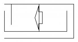
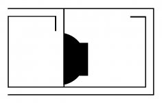
I moded my 6th order bp idea to fix that air-compression thing and here it's (just a sketch, not scaled).
Could someone please sim this for me, cos I don't know how to...?
I'm now ready to build this and looking for dimensions.
If space is your concern, I have enough space in the room to place any large of a box.
For t/s reference, here's the driver I'm gonna use.
12TBX100 LF Drivers - B&C Speakers
Thanks in advance...")
Could someone please sim this for me, cos I don't know how to...?
I'm now ready to build this and looking for dimensions.
If space is your concern, I have enough space in the room to place any large of a box.
For t/s reference, here's the driver I'm gonna use.
12TBX100 LF Drivers - B&C Speakers
Thanks in advance...
Attachments
Last edited:
Bro, welcome back!Tbx12, in a ROAR or paraflex 8th order ‘pipe’ . Unique and violent bass, Fun, not average or ordinary.... search either and be rewarded with a reference to listen to?
Okay, you already know I'm not a techie of subs, just thinking how my design would be, but when there's a reference to the "8th order paraflex" I gotta ask this, and I have to, my point, as far as I know, two wavelengths (although with unequally tuned frequencies) meeting one-another (even right at the exit) will cause some acoustic criss-cross and wave cancellation in result will be, now, I could see in almost every "8th order paraflex" design it seems to happen, cos these designs have one exit for both airflows, I fixed that in the design on this new thread...???
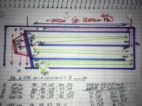
The paraflex combined those and can use a 3:1 ratio similar to an offset driver TL might prefer 100cm before 200cm. (300total, but 400 affective in pressure phase) but its all skewed in expanding shaped paths and segmented area changes etc etc
.
In straight pipe, The long path is 300cm, then the short path will be 100cm. If end fired into each perfectly. (No offset)
The long is 240cm then the short is 80cm.
When combined with no other offsets or flate rates, etc you get the combo at the concentric exit(0.01cm) thats impossible to create(geometry and radius of a driver basket and vent centerline ).
Examples to show this as cancelation fully or patially at the same points of interest are divided in tiers of the shorter path length in either direction or stacked onto the other in many ways, including combined exit lengths from another impedance landmark.
Imagine a 200cm/sec pulse in a pipe, 300cm long with driver at 100cm from closed end. Then a 100cm/sec pulse, and then a chamber behind the cycle that expands and slows up the surge like the exhaust on a cr500 or kx500 or old bulltaco dirtbike? Now that pulse timing and backwave are regularred with a surge tank or something? Its really intersting and kinda hard to mix it all together as a ‘speaker’ but i keep building stuff that exploits that more and more and in weird ways i dont think i even understand in the slightest, lol! But its working? As a bass dumpster at least...
so, theres two helmholtz in yours or one? im not sure but i have an isobaric version of that ? Its short vent is bigger(not longer).
Last edited:
I moded my 6th order bp idea to fix that air-compression thing and here it's (just a sketch, not scaled).
Could someone please sim this for me, cos I don't know how to...?
I'm now ready to build this and looking for dimensions.
If space is your concern, I have enough space in the room to place any large of a box.
For t/s reference, here's the driver I'm gonna use.
https://www.bcspeakers.com/en/products/lf-driver/12-0/8/12tbx100
Thanks in advance...
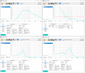
I think the shape needs to be changed for a 6th. Here is a quick run on 1000W. Ports are not that different in length, but the boxes are.
Attachments
Last edited:
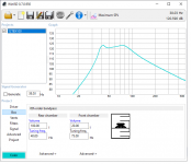
There ya go! Except one must note the short comings of that program are very real. I stopped using it quickly after my first look as horn response later showed the reality of ‘lumped sums as pressure vessels’?
Horn response drops a dime on the 6/8th order pipes ive made and i cant even believe how the impedances mimic the first few in tiers so well. Very well played by David mcbean! In fact, most folded t TLs might need to consider the TH sime with 0.01cm as the last segment. If chasing that void around up top to see where it went or is potentially.
Horn response drops a dime on the 6/8th order pipes ive made and i cant even believe how the impedances mimic the first few in tiers so well. Very well played by David mcbean! In fact, most folded t TLs might need to consider the TH sime with 0.01cm as the last segment. If chasing that void around up top to see where it went or is potentially.
Bro, welcome back!
Okay, you already know I'm not a techie of subs, just thinking how my design would be, but when there's a reference to the "8th order paraflex" I gotta ask this, and I have to, my point, as far as I know, two wavelengths (although with unequally tuned frequencies) meeting one-another (even right at the exit) will cause some acoustic criss-cross and wave cancellation in result will be, now, I could see in almost every "8th order paraflex" design it seems to happen, cos these designs have one exit for both airflows, I fixed that in the design on this new thread...???
The paraflex (example of a generic version) signal traveled 100cm from its origin while its polar opposite from the other side traveled 300cm in three 100cm increments. Except for some changes in CSA those relate to the bandwidth and its fundamental frequency from (center of an imaginery place?) if using the middle frequency, its a squiggle in phase shown at a point related to 28.6-143 hz. you drift outta those pipes at 100cm and 300cm. If you roll out the combo of phase from zero to 90 to (180) and -90/270 and 360/0 and so on.. its the same spot(in a sim using those generic lengths)
I know what you mean by adding another length between the exits, but they are not aligned to share that properly. Pick any division of that but the csa change is twisting it as well? so i suggested pipe geometries to make it less impossible to envision or even sim the potential.
In a bass reflex version its so skewed theres no way to do that? I dont think(?). Its not based on a column of air length to vent , only a pressure shifted on a slug of air it relieves at a certain point? (A lot alike but not in this assumption)? You need to align a mass and spring of two hugely dufferent rates. . The other is all one or assumed its all a column and that springrate. Its ‘easier’ for us mere mortals of math and such
Last edited:
Alright, now it's clear, I guess you were talking for this whole time since we met about the "air velocity", I always had this doubt, if air pressure is manipulated between the chambers to flow one faster than the other (just realized the 3:1 ration you explained plus short vent big instead of long), the criss-cross won't occur, problem solved!The paraflex combined those and can use a 3:1 ratio similar to an offset driver TL might prefer 100cm before 200cm. (300total, but 400 affective in pressure phase) but its all skewed in expanding shaped paths and segmented area changes etc etc
.
In straight pipe, The long path is 300cm, then the short path will be 100cm. If end fired into each perfectly. (No offset)
The long is 240cm then the short is 80cm.
When combined with no other offsets or flate rates, etc you get the combo at the concentric exit(0.01cm) thats impossible to create(geometry and radius of a driver basket and vent centerline ).
Examples to show this as cancelation fully or patially at the same points of interest are divided in tiers of the shorter path length in either direction or stacked onto the other in many ways, including combined exit lengths from another impedance landmark.
Imagine a 200cm/sec pulse in a pipe, 300cm long with driver at 100cm from closed end. Then a 100cm/sec pulse, and then a chamber behind the cycle that expands and slows up the surge like the exhaust on a cr500 or kx500 or old bulltaco dirtbike? Now that pulse timing and backwave are regularred with a surge tank or something? Its really intersting and kinda hard to mix it all together as a ‘speaker’ but i keep building stuff that exploits that more and more and in weird ways i dont think i even understand in the slightest, lol! But its working? As a bass dumpster at least...
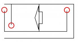
so, theres two helmholtz in yours or one? im not sure but i have an isobaric version of that ? Its short vent is bigger(not longer).
If you mean the below red markings by "helmholtz", there are three...
Attachments
The paraflex (example of a generic version) signal traveled 100cm from its origin while its polar opposite from the other side traveled 300cm in three 100cm increments. Except for some changes in CSA those relate to the bandwidth and its fundamental frequency from (center of an imaginery place?) if using the middle frequency, its a squiggle in phase shown at a point related to 28.6-143 hz. you drift outta those pipes at 100cm and 300cm. If you roll out the combo of phase from zero to 90 to (180) and -90/270 and 360/0 and so on.. its the same spot(in a sim using those generic lengths)
I know what you mean by adding another length between the exits, but they are not aligned to share that properly. Pick any division of that but the csa change is twisting it as well? so i suggested pipe geometries to make it less impossible to envision or even sim the potential.
In a bass reflex version its so skewed theres no way to do that? I dont think(?). Its not based on a column of air length to vent , only a pressure shifted on a slug of air it relieves at a certain point? (A lot alike but not in this assumption)? You need to align a mass and spring of two hugely dufferent rates. . The other is all one or assumed its all a column and that springrate. Its ‘easier’ for us mere mortals of math and such
Thanks once again for making your explanations far simpler...
Yes, longer port is triple the shorter port, the smart idea behind this so-called "parafelxing" and what exactly I was missing in my design, I'm getting this now.
Considering all these, I made a far sophisticated design, no "helmholtz" (but still a 6th order, not 8th), agree on this...?
Attachments
IMO though, this program seemed to have misinformed the builder, especially in slot-ported ones.I think the shape needs to be changed for a 6th. Here is a quick run on 1000W. Ports are not that different in length, but the boxes are.
However, my sketch is not drwan to a certain scale (the front chamber should be smaller for example).
True!There ya go! Except one must note the short comings of that program are very real. I stopped using it quickly after my first look as horn response later showed the reality of ‘lumped sums as pressure vessels’?
Horn response drops a dime on the 6/8th order pipes ive made and i cant even believe how the impedances mimic the first few in tiers so well. Very well played by David mcbean! In fact, most folded t TLs might need to consider the TH sime with 0.01cm as the last segment. If chasing that void around up top to see where it went or is potentially.
Im not very much into the ported box stuff or well versed in the bass reflex higher order versions except maybe a doublebass reflex or MLTL ?. Basically if run the rear output in 80 cm of its 1200cm2 area needed. And then put a 3 or 4 segment parabolic expansion out front and join them in close proximity at a merged exit. Or at the driver, in series with that 1200cm2 , you have a very fun 12 tbx100. And likely some proven ideas/plans you can tweak into the similar?
This is Swedish Bass served with a hammer and a whip���� It makes girls fall
Over from vibrations in reproductive parts!? )rumor has it(
Martinsson's Blog - ROAR12
This is Swedish Bass served with a hammer and a whip���� It makes girls fall
Over from vibrations in reproductive parts!? )rumor has it(
Martinsson's Blog - ROAR12
Last edited:
Wait, parabolic should be kinda tapped version?Im not very much into the ported box stuff or well versed in the bass reflex higher order versions except maybe a doublebass reflex or MLTL ?. Basically if run the rear output in 80 cm of its 1200cm2 area needed. And then put a 3 or 4 segment parabolic expansion out front and join them in close proximity at a merged exit. Or at the driver, in series with that 1200cm2 , you have a very fun 12 tbx100. And likely some proven ideas/plans you can tweak into the similar?
This is Swedish Bass served with a hammer and a whip���� It makes girls fall
Over from vibrations in reproductive parts!? )rumor has it(
ROAR is a bit complicated design, rear air comes to the exit via TL in both sides, and front has infinite space to exit, can't imagine how ROARing its output will be...
Lol!! Im not sure either but they all look funny but sound funny tooo(in a good way). Still need another fold and ipper tier on this one that zigzags back in another larger pipe segment as long as these that proceed it. A lo filter or resonator doen the middle maybe as well?
Attachments
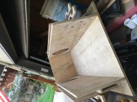
Is this one of your builds...?Lol!! Im not sure either but they all look funny but sound funny tooo(in a good way). Still need another fold and ipper tier on this one that zigzags back in another larger pipe segment as long as these that proceed it. A lo filter or resonator doen the middle maybe as well?
I'm seeing this kinda TL for the 1st time, mostly in TLs one side of the driver is sealed, but in this front air comes 2-way to rear and rear is open-air as well, thinking thinking...Thats this (pic), but ignoring the pink ‘extras’ and exit detail as theyre a seperate part of a different function and more ‘bolt ons’.
- Status
- This old topic is closed. If you want to reopen this topic, contact a moderator using the "Report Post" button.
- Home
- Loudspeakers
- Subwoofers
- How about this...?