This can rather be a passive low-pass filter than a sub...Yeah, it seems the offset driver position runs bandwidth up to the 5 (1/4 wave harmonic instead of the null often seen at ~ 3 x the ( qw )fb.. if i sim the full
Line with no offset 3/3 and the line after offset 2/3 it fills right in overlayed.

It seems to work in many many more ways repetatively!����! To which and when its diminished its value is ‘folding’. but folding is a connundrum. A convenient shape, or an acoustical relevant position? 3 folds is great for one harmonic but defines the next(it seems). Building on that using the other side of the driver is going to build a messy spike in response you can ‘eq’ off(?), but meanwhile you have potentially created an aligned phase in a full cycle and cone control centered on a pressure null dividing it?
I cant tell wtf its actually doing, but compared to a sealed box in a room with boundary its the silly experimental attempt to try and find a vented solution to an issue often given sealed as a solution...?
I cant tell wtf its actually doing, but compared to a sealed box in a room with boundary its the silly experimental attempt to try and find a vented solution to an issue often given sealed as a solution...?
Last edited:
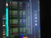
Heres the abuse of use of nearly perfect ‘aligned’ sections of a fundamental base is used (so to speak).
Its 100 cm used over and over while maintaining a seperation in the polarities of the outputs that appears acceptable to the immediate bandwidth or the most within reason including an EQ at the top snipping off excessive response to the combined 100cm interval.
Its 100 cm used over and over while maintaining a seperation in the polarities of the outputs that appears acceptable to the immediate bandwidth or the most within reason including an EQ at the top snipping off excessive response to the combined 100cm interval.
Attachments
How would you take below one (no foldings or 90s/180s or whatever, just as simple as two straight pipes), no complications here right...???It seems to work in many many more ways repetatively!����! To which and when its diminished its value is ‘folding’. but folding is a connundrum. A convenient shape, or an acoustical relevant position? 3 folds is great for one harmonic but defines the next(it seems). Building on that using the other side of the driver is going to build a messy spike in response you can ‘eq’ off(?), but meanwhile you have potentially created an aligned phase in a full cycle and cone control centered on a pressure null dividing it?
I cant tell wtf its actually doing, but compared to a sealed box in a room with boundary its the silly experimental attempt to try and find a vented solution to an issue often given sealed as a solution...?
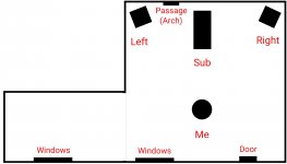
Well, my living room (where my sub will be living) is 4000 sq. ft. (20*20*10), a pretty big space (a sketch below for reference) for a sealed cab to handle, that's why I'm gonna go for 6th order instead (much better spl), but still I'm thinking about nearfield to grab its optimum.
Attachments
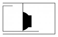
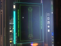
Again, its a pic of helmholtz with no info. Far too random to know or even guess. The only way to guess would be a qw design and the proportions in length offer a guess to the tunings on each side in parallel.Otherwise a pic is almost of zero value without exact dimensions.
If you drew two pipes off each side of the driver and they shared a length in a ratio and the space between them at the open ends would make guessing easy if that was 1:3, 4 or 2:6, folded, 2.... etc
The model solodaat did in win ISD is great, but it just needed a driver offset to ensure the oipe modes didnt screw up the intended sim. Some things hornresponse allows.
Bare with me .
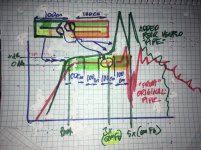
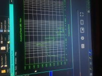
In the red response we have a standardd qw pipe., if we put a stub at the top of it upstream of the driver the red ravine fills in and shifts up to the place as drawn(before that it would be at the left line drawn vertically.
If we then add that same added length to the rear output of the driver we create the green response shape or a shifted version of it similar to the red had done , if you shuffle what you ‘add’ to the qw pipe off the ‘front’ (or rear)
But another approach is to place the added portion after the qw pipe joins at its exit(the driver rear) . And before that you can add the same as you did originally to the ‘front’ pipe and its sufdemly a HP filter at the point it reaches that length (again). However, if sized thin, and longer and longer, its a filter and not cancelling . And now youre a really huge box, but nobody can deny its very interesting with a potential for loud and wide bandwidth.
With a careful application of all of that(second part) the response is what i have in my garage waiting for one new step in the sim to put the iving on that cake to mount the very last partt described .
The drivee i used isvery much like the 12tbx100 and sometimes share cabinet designs if the tbx gets a but more expansion and a higher tune.????
.In the red response we have a standardd qw pipe., if we put a stub at the top of it upstream of the driver the red ravine fills in and shifts up to the place as drawn(before that it would be at the left line drawn vertically.
If we then add that same added length to the rear output of the driver we create the green response shape or a shifted version of it similar to the red had done , if you shuffle what you ‘add’ to the qw pipe off the ‘front’ (or rear)
But another approach is to place the added portion after the qw pipe joins at its exit(the driver rear) . And before that you can add the same as you did originally to the ‘front’ pipe and its sufdemly a HP filter at the point it reaches that length (again). However, if sized thin, and longer and longer, its a filter and not cancelling . And now youre a really huge box, but nobody can deny its very interesting with a potential for loud and wide bandwidth.
With a careful application of all of that(second part) the response is what i have in my garage waiting for one new step in the sim to put the iving on that cake to mount the very last partt described .
The drivee i used isvery much like the 12tbx100 and sometimes share cabinet designs if the tbx gets a but more expansion and a higher tune.????
Attachments
I moded my 6th order bp idea to fix that air-compression thing and here it's (just a sketch, not scaled).
Could someone please sim this for me, cos I don't know how to...?
I'm now ready to build this and looking for dimensions.
If space is your concern, I have enough space in the room to place any large of a box.
For t/s reference, here's the driver I'm gonna use.
https://www.bcspeakers.com/en/products/lf-driver/12-0/8/12tbx100
Thanks in advance...
Still to know these measurements to sim it for you
Sorry for being late to reply, was quite busy...Again, its a pic of helmholtz with no info. Far too random to know or even guess. The only way to guess would be a qw design and the proportions in length offer a guess to the tunings on each side in parallel.Otherwise a pic is almost of zero value without exact dimensions.
If you drew two pipes off each side of the driver and they shared a length in a ratio and the space between them at the open ends would make guessing easy if that was 1:3, 4 or 2:6, folded, 2.... etc
The model solodaat did in win ISD is great, but it just needed a driver offset to ensure the oipe modes didnt screw up the intended sim. Some things hornresponse allows.
I think you're bit confused of what I've drawn. Bro, it's just a sketch, if you remember the sketches I posted on the previous thread, they all have a single 90° at least that leads to "air compression (a sudden 90° drift will dissipate air mass, as a result some air will reflect back)", so for a better airflow I dully changed my original design to none of 90°s and posted it here, so this picture we're talking about has no propotions, just a sketch it's, every propotion is yet to be done at the simulation, which I'm asking someone to help in cos I really don't know how to.
Okay, now I'm barely realizing what you're attempting to educate me, can have a better knowledge if you wish to highlight this on the design I've ORIGINALLY done (as you stated).Bare with me
In the red response we have a standardd qw pipe., if we put a stub at the top of it upstream of the driver the red ravine fills in and shifts up to the place as drawn(before that it would be at the left line drawn vertically.
If we then add that same added length to the rear output of the driver we create the green response shape or a shifted version of it similar to the red had done , if you shuffle what you ‘add’ to the qw pipe off the ‘front’ (or rear)
But another approach is to place the added portion after the qw pipe joins at its exit(the driver rear) . And before that you can add the same as you did originally to the ‘front’ pipe and its sufdemly a HP filter at the point it reaches that length (again). However, if sized thin, and longer and longer, its a filter and not cancelling . And now youre a really huge box, but nobody can deny its very interesting with a potential for loud and wide bandwidth.
With a careful application of all of that(second part) the response is what i have in my garage waiting for one new step in the sim to put the iving on that cake to mount the very last partt described .
The drivee i used isvery much like the 12tbx100 and sometimes share cabinet designs if the tbx gets a but more expansion and a higher tune.????
It seems to me like two TLs joint together at the driver point, good concept.
I got this question btw, is the poor group-delay in 6th order (especially in parallel like my design) true???
I've chosen that B&C but gotta know by reading t/s that it resonates above 42hz (Fs), will it get down to 20hz (the bass threshold I'm looking for)?
I'm glad if you would bro, read my replies...Still to know these measurements to sim it for you
Could someone please sim this for me, cos I don't know how to...?
I'm now ready to build this and looking for dimensions.
Your link doesn't work, you put a link in a link.
All you needed to post is this:
12TBX100 LF Drivers - B&C Speakers
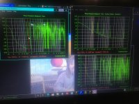
Here is a quick run on 1000W. Ports are not that different in length, but the boxes are.
Interesting! FWIW HR limits power to ~378 W/9 mm Xmax.
What are the lengths? I just used 20 cm, the min. distance to back wall based on driver depth.
Attachments
I'm glad if you would bro, read my replies...
Yeah, im not sure i ever was able to describe what i thought you were . I dunno if you can look but GM(Greg) has broken it up into pieces (20cm portions) and i previously did 40 (same thing essentially but squares to cubes in youre chambers) to mimic all dimensions as they would fit as drawn. But a port area and the details or your ‘exit and lengths apart’ as well as 90 degrees vs 180 degrees were important ? Have a go at plugging it all in from the txt file. The speaker Jedi has constructed
Yeah, as 40 cm it still just created a tall skinny rippled two bump if trying to get at what the pics appeared to be conveying. Though what he had was almost exactly where this is in Isobaric
rF p3 d2
Sd
570
Re3.2 Le 4
Vas 57
fs 26
Qes .53
Qms 6.7
Xmsx 13
Pfms 600
Chambers are 48 liters and 300 cm2 wraps around at 240 cm length as the vent is just rear chamber fof an excuse to play with cone control and stuffing
I Cant really get a tbx to work where the other TS parameters above almost do alright in the shape as it appears(abbreviated the short side port to nearly nothing but open rear chamber volume at 1200cm2... x 40 cm.
- Status
- This old topic is closed. If you want to reopen this topic, contact a moderator using the "Report Post" button.
- Home
- Loudspeakers
- Subwoofers
- How about this...?