Apologies for tardy reply…life events and all.… But ACE-Bass has resistor "R"
As mentioned in Post #18 , the amplifier current is used to create the virtual components that define the output impedance. Voltage across a resistor between woofer and ground is an easy way to sample amplifier current. You could also use a current transformer if you wanted to avoid power losses in the resistor. Sampled amplifier current can be used to create amplifiers with output impedance ranging from simply resistive (- Re, to near + infinite) to capacitive, inductive, or combinations thereof. This is not corrective MFB. However, when that resistor between woofer and ground is used as part of a bridge arrangement, it allows extraction of the voltage generated by the velocity of the voice coil in the magnetic field gap(ie back EMF). Here you have a signal proportional to motion of the cone that can be used for corrective MFB.
If you are unable to evaluate detailed circuit behavior from a schematic(not too many people can), your alternatives are to use a circuit simulator like LTSpice to analyze it for you, or build and measure. Having done both myself, please re-read Post #15 which describes the actual measured behavior of ACE-Bass and bridge MFB systems, not notional behavior based on presence of a resistor in a circuit diaphragm. The MFB system responds correctively to changes(or errors) in the woofer/enclosure system. The ACE-Bass system does not.…The ACE-Bass amp uses that feedback correctively…
This notable difference in measured(and modeled) performance has to be acknowledged before you can appreciate methods and details of what is going on. My hope was that providing examples of actual behavior (along with conceptual view of how behavior is realized) would help you and others understand what the circuit is actually doing. Its operation is fundamentally different from corrective MFB. Notice that I didn’t say better, just different. You would be very close to the mark if you instead complained that Ace-Bass was just an overly complicated way of performing EQ.
Ok, thanks for clarification….nothing unfamiliar in that list. I thought you were implying there was something psychoacoustic related that was being missed.…Bad behaviour includes HD, as you mention, but also shortcomings in playing transients, continuing to rumble-on at the off-set of a note, etc.
On a first thought basis, I would have my doubts, but actually, the ACE technique can reproduce the lowest frequency band with ease and effective damping - depending on implementation that I consider to be tricky.
The complex magnetic force product is reflected in the sense resistor. There is difficulty in damping low frequency resonant amplitudes and there is difficulty in designing low frequency tuned amplifiers. It is a matter of accomplishing sufficient damping while avoiding instability.
The complex magnetic force product is reflected in the sense resistor. There is difficulty in damping low frequency resonant amplitudes and there is difficulty in designing low frequency tuned amplifiers. It is a matter of accomplishing sufficient damping while avoiding instability.
Good thoughts.
MFB with Rice-Kellogg drivers works OK since the phase doesn't go too crazy in the passband and if you don't push the amount of correction (say, not beyond 25 dB... which is a great improvement for distortion and cone rumbling).
My impression is that the stability issues of these systems are at the freq edges, as with many servo systems. Both high and low ends and the ability to steer the amp clear of no-win phase-and-amplification issues at the edges that takes some care.
B.
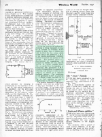
While attempting to organize my electronic archive on MFB, found the attached clipping: an even earlier description by Williamson(yes, that Williamson) for using bridge arrangement to extract cone velocity for MFB use was published in 1947 Wireless World, also includes inductance compensation in the schematic.… Previous experimenters like Clements did identify the potential need to balance out the VC inductance, but only mention using an appropriately ratioed inductance to do it
Attachments
Smart folks in olden days.
BTW, using a bridge approach puts the ground reference (to the right side of the transformer) in limbo. Using a transformer (as in most of the old tube amps*) allows the designer to put the ground right at one of the terminals and feedback at the other.
B.
* there was a multi-tube cathode-follower amp that had no transformer
- Home
- Loudspeakers
- Subwoofers
- Active Servo Subwoofers