So in other word the graph you posted only tells us about one spot in the response and certainly would suggest that fibre is better than foam.
dave
I think that lower fibre density would not only reduce the low frequency attenuation, but also make the rolloff slope shallower. It would then be worse than the foam, when the comparison is made on the basis of equal low frequency atten.
Dave, you seem a little harsh. The foam and fiber graphs have very similar shapes. It would not be hard to mentally extrapolate between the no fiber, no foam curve and the fiber curve to see that with less fiber (to match output with the foam curve) the peaks and troughs would be exaggerated.
His lack of hard data is not a big deal to me. His recollection, and logic, given the data that he does have, seems like they match.
His lack of hard data is not a big deal to me. His recollection, and logic, given the data that he does have, seems like they match.
The graph does not tell us much. More data needed.
Yes, if the fibre density was reduced you would get less absorbtion in the line, but in both the fibre and foam plot lines into the midrange are below the bottom of the chart.
Given the existing data there is lots of room for the midrange attenuation of the fibre to decrease and still be better than the foam.
In almost any TL, stuff above 500 Hz is not of much concern. One can see both the black & red lines plumment about there.
Hopefully one is using various geometric solutions to dealing with the lowest unwanted ripple (3) so the damping need only absorb stuff above that (ie 5 and higher).
dave
We
The foam and fiber graphs have very similar shapes.
Exactly. And at the densities shown the fibre has some 5 dB greater attenuation. And both start fallin gbelow about 100 Hz.
To show anything realistic one would need to adhust the density levels so as much of those 2 curves are anbout the same and then see where things are different.
dave
I think that lower fibre density would not only reduce the low frequency attenuation, but also make the rolloff slope shallower. It would then be worse than the foam, when the comparison is made on the basis of equal low frequency atten.
Exactly
Does the tapered line model support a constant foam thickness, rather than a constant percentage cross section?
I'm thinking of the conventional situation of glueing the foam to the line walls.
Exactly: in all blocks the foam is modelled as a sheet of defined thickness and is independent of the shape of the TL.
There is no doubt that fibre stuffing has a huge faff factor. You have to tease it out to get the right density
i tease it as much as posible and then if i need higher density just push more in. I see far to many instances of insufficient fluffing.
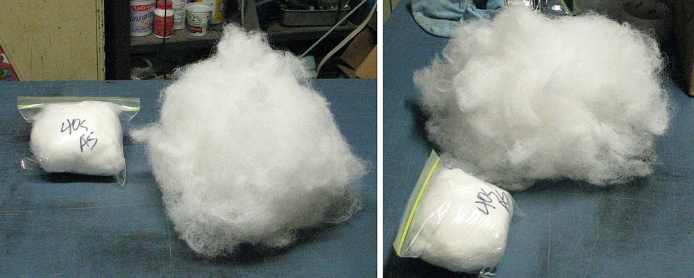
In the bag and out of the bag well teased.
Besides its absorbion characteristics because it holds its loft very well. Mix it 50/50 with say wool, for different characteristics.
dave
I like the foam idea, the expensive eggcrate mattress open cell stuff in stategic areas(liner, not constictor) and then loose, not crammed polyfil to figure out the details or not choke the center pat to exit.
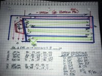
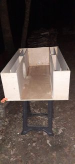
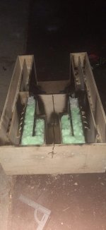
But then i started cutting an plumbing and bypassing or dead end stubs with the foam... the things that occur when imducing a Venturi shape or bowtie look to the ‘big picture’ or short circuit ‘velocity’ to an area of frequency concern, vs blocking tgem off or using them ‘bare/unstuffed’ was bizarre and amazing in the tapped entries (not this exact one, another style before it).
But then i started cutting an plumbing and bypassing or dead end stubs with the foam... the things that occur when imducing a Venturi shape or bowtie look to the ‘big picture’ or short circuit ‘velocity’ to an area of frequency concern, vs blocking tgem off or using them ‘bare/unstuffed’ was bizarre and amazing in the tapped entries (not this exact one, another style before it).
Attachments
to be fair, the issues were a bit over the top and fresh TS parameters and new amp equipment mixed up the ‘results a bit, so theres no legit info to share honestly.. but the cancelling in the offset areas was bad. But the stuffed and unstuffed response to the mid band Notch from hell became a smooth round and rising, to counter any house curve, bubble of bass response and total game changer for this experiment gone wrong(lots of weird stuff to try and learn in this and lots of ways to get confused(or be optimistic til the end)...
Attachments
Colin, the owner of EJJordan Design, dedicated a blog to SpicyTL ")
Ikigai - a compact TL loudspeaker designed using SpicyTL - E J Jordan Designs
Ikigai - a compact TL loudspeaker designed using SpicyTL - E J Jordan Designs
Just been trying out the software, but I'm not sure about the S_foam parameter. It states that this is the cross-sectional area of the foam, but how does that work with the tapered line? The foam area would need to reduce in proportion to the line area, but there is only one parameter to enter.
Just been trying out the software, but I'm not sure about the S_foam parameter. It states that this is the cross-sectional area of the foam, but how does that work with the tapered line? The foam area would need to reduce in proportion to the line area, but there is only one parameter to enter.
The cross-sectional area of the foam is independent from the line shape and must not be reduced in proportion to the area of the line.
If you want to increase the foam thickness in a line section, you have to add a new block and define the new thickness in that block. This is exactly what you would do in a physical TL by adding a sheet of foam only in one section of the line.
Yes but the foam cross-sectional area will be approx given by the product of the line circumference and the foam thickness. But that will reduce in direct proportion to the line length for a tapered line. It won't be constant as it would for a straight line.
Suppose my line is 24x15cm at one end and 4x15cm at the other, and the foam thickness is 1.5cm.
The foam cross-sectional area will be 117cm^2 at the start and 57cm^2 at the end.
Last edited:
Yes but the foam cross-sectional area will be approx given by the product of the line circumference and the foam thickness. But that will reduce in direct proportion to the line length for a tapered line. It won't be constant as it would for a straight line.
Suppose my line is 24x15cm at one end and 4x15cm at the other, and the foam thickness is 1.5cm.
The foam cross-sectional area will be 117cm^2 at the start and 57cm^2 at the end.
Now I get what you mean. Basically it's a matter of lining the side walls of a tapered TL with a very high taper ratio. I've never considered this possibility (normally it's enough to line the side with constant width), but actually it could be useful to modify the model so that the cross-sectional foam area is defined at the beginning and at the end of the block.
For now, you can try using the straight_fiber block and changing the material parameters (c_fiber and K_fiber) to be the same as the foam parameters. This block allows you to define the cross-sectional area as a percentage of the total TL surface. Let me know.
I thought I would do a comparison between SpicyTL and the MJK software using a Bailey style TL as an example, and the Satori MW16P-8 driver. Chamber, 1st and 2nd line segments are stuffed, 3rd line segment is empty:

Line profile:

MJK simulation result:

Predicted response is -3dB at 45Hz and -6dB at 36Hz. Port output is very low Q, peaking at 45Hz.
Now using SpicyTL foam models, with 1.5cm thick foam in the chamber, 1st and 2nd line segments. Block diagram:

And simulation result:

The overall -3dB point is about the same, maybe slightly lower, and the top-end ripple is very similar. However, the broad dip between 100 and 170Hz is quite different. Whether this is a genuine result of using the foam, or a model artefact is unknown.
Next step will be to try SpicyTL with the fibre filled line models.
Line profile:
MJK simulation result:
Predicted response is -3dB at 45Hz and -6dB at 36Hz. Port output is very low Q, peaking at 45Hz.
Now using SpicyTL foam models, with 1.5cm thick foam in the chamber, 1st and 2nd line segments. Block diagram:
And simulation result:
The overall -3dB point is about the same, maybe slightly lower, and the top-end ripple is very similar. However, the broad dip between 100 and 170Hz is quite different. Whether this is a genuine result of using the foam, or a model artefact is unknown.
Next step will be to try SpicyTL with the fibre filled line models.
Good job.
I would like to make a few considerations:
When designing a TL with foam you have to plan for a shorter length than a TL with fibre. Also the simulation graph with foam immediately suggests that to optimise the response you have to shorten the line. You will see that the left side of the graph will rise and you will have a better f3, but what will also happen is that the port output will be higher and you may have a further increase in ripple as a result. I suggest you also fill in the last segment of TL, which usually has an unsuspected effect on the linearisation of the response. In order to make the simulation even more accurate, I also recommend taking bends into account.
What are the damping parameters of the fibre TL? I've never tried MJK's software and don't know how the presence of damping material is handled. The graph is very flattened and elongated and you can't really assess the amount of ripple.
It will be interesting to see the two simulations with fibre compared.
I set the tapered line lengths such that they already included the bends, assuming the centre line of each segment defines its length.
Just tried reducing the length of each line segment (from 0.44 to 0.35m) but the only effect was to shift the whole plot to the right. That is, it tuned higher in freq. The general shape of the response was the same, including the large first dip.
Adding foam to the final line segment reduced the ripple slightly, but the rest of the plot was largely unchanged.
The port output plot looks very odd, peaking around 90Hz.
The MJK software plot is exactly the same as the SpicyTL plot, namely 10 to 1000Hz (log) and 60 to 110dB. The stuffing density was set to 1lb/cu.ft in the chamber and first line segment and to 0.5lb/cu.ft in the 2nd segment. 3rd segment has no stuffing. From experience I know that making the stuffing density reduce roughly in proportion to the line taper gives best results.
- Home
- Loudspeakers
- Subwoofers
- SpicyTL - Transmission Line Simulation Model