5. Finally, can LTspice's more advanced capabilities, such as parameter sweeping and Monte Carlo analysis, be used with SpicyTL?
Sure, you can use all the powerful features of LTspice.
More, with a good knowledge of electroacoustics and some familiarity with the software you can model virtually any design.
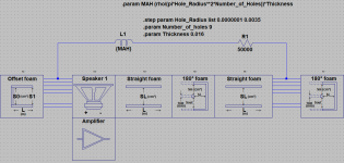
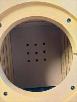
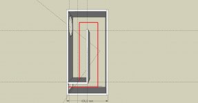
For example the configuration in Fig. 13 shows the effect of a few holes (foto 2) drilled in the first internal divider panel of the TL.
The idea was to slightly reduce the ripple in the response by offloading some of the pressure generated by the driver to an area close to 1/3 of the length of the TL. Something we could call "virtual offset driver".
In figure 14a you can see the measurement with and without holes and in figure 14b the relative simulation implemented with the command .step param
Attachments
"Modeling the effect of a TL partially filled with absorbent material is the main feature of SpicyTL"
It is correct to assume this is referred to a TL with internal surfaces covered with some egg crate foam of standard thickness (2" to 3") and not totally filled?
Yes, exactly.
Very, very cool!
Thanks for your hard work on this. It makes TL simulation accessible to more people.
One question; would it be difficult to modify the modelling to include the option of a mass loaded TL? In other words, to add the option of terminating the line with a vent, rather than a simple open end.
Hi Cogitech,
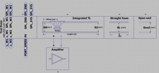
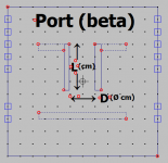
the port block is now ready and I'm going to add it to SpicyTL very soon. This will be very useful to simulate bass reflex speakers (taking into account reflections on the longer side) or TL's with offset port.
Reflecting on your request I realized that you can simulate an MLTL by simply adding a TL section of the desired value (area and length) to the end of the TL. You can for example use the straight_foam block. Don't forget to terminate the port with the open_end block.
Attachments
Hi Andrea.
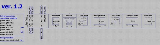
Is my list of spicy components correct for this tline design?
https://www.diyaudio.com/forums/attachment.php?attachmentid=921880&stc=1&d=1613238937
https://www.diyaudio.com/forums/attachment.php?attachmentid=921881&stc=1&d=1613238937
Is my list of spicy components correct for this tline design?
https://www.diyaudio.com/forums/attachment.php?attachmentid=921880&stc=1&d=1613238937
https://www.diyaudio.com/forums/attachment.php?attachmentid=921881&stc=1&d=1613238937
Attachments
Last edited:
Hi deepboy,
since it is not possible to insert the driver in the development of a fold, yours is a good approximation.
However, I think it would be better to take into account the exact length of the offset and neglect the first 90° bend (whose volume is anyway altered by the presence of the driver).
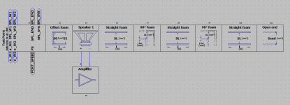
I would do this:
since it is not possible to insert the driver in the development of a fold, yours is a good approximation.
However, I think it would be better to take into account the exact length of the offset and neglect the first 90° bend (whose volume is anyway altered by the presence of the driver).
I would do this:
Attachments
Excellent work!
Have you made any measurements of the attenuation versus frequency for foam-lined transmission lines in comparison to fibre stuffed lines?
I regularly use the Martin J King software but that only models dacron fibre stuffing. I once asked Martin about the use of foam, and he said measurements he had seen indicated that it behaved mainly as a means of restricting the line cross sectional area, rather than absorbing the sound.
On the other hand, Ivan Leslie of IPL Acoustics is adamant that foam is better (albeit without providing any evidence).
Excellent work!
Have you made any measurements of the attenuation versus frequency for foam-lined transmission lines in comparison to fibre stuffed lines?
I regularly use the Martin J King software but that only models dacron fibre stuffing. I once asked Martin about the use of foam, and he said measurements he had seen indicated that it behaved mainly as a means of restricting the line cross sectional area, rather than absorbing the sound.
On the other hand, Ivan Leslie of IPL Acoustics is adamant that foam is better (albeit without providing any evidence).
Thank you,
I have experimented with different fibrous materials (mainly Dacron, Polyfill, glass wool and natural long fibre wool) and found them all to be quite similar. None of these materials have a significant impact on sound speed, not even natural wool which does not have the miraculous properties praised in some past publications.
I have also tried other non-fibrous acrylics with poor results. Then I tried foam and the results were so impressive that I stopped looking for alternative materials to fibre and concentrated exclusively on this material with appropriate modifications to the model.
I have developed several models to simulate the fibre, but integrating them into SpicyTL requires a lot of work that I don't think is worth doing. However, in SpicyTL you will find a straight_fiber block that is useful for making some comparisons on simple straight TL sections.
I'm not aware of Martin King ever experimenting with foam, but he seemed very interested in my results.
I haven't really discovered anything new, the most famous TL manufacturers use (or have used) foam, and it's clear that they don't do it just for the ease of use.
Just been reading through the very interesting articles on your site.
In the article on foam:
The Simulation with Foam – Transmission Line Speakers
... you mention that the line is modelled as two lines in parallel, one with foam and one without.
Does this mean that the overall transfer function of the line comprises two paths: one with little attenuation, and the other with a frequency dependent (lowpass) roll-off?
And does that in turn mean that at high frequencies, where the 'air path' is dominant, the overall ripple in the frequency response of the speaker will be higher than when using fibre stuffing (which only has one path in its line)?
Just been reading through the very interesting articles on your site.
In the article on foam:
The Simulation with Foam – Transmission Line Speakers
... you mention that the line is modelled as two lines in parallel, one with foam and one without.
Does this mean that the overall transfer function of the line comprises two paths: one with little attenuation, and the other with a frequency dependent (lowpass) roll-off?
And does that in turn mean that at high frequencies, where the 'air path' is dominant, the overall ripple in the frequency response of the speaker will be higher than when using fibre stuffing (which only has one path in its line)?
There are two parallel paths, but they are closely interlinked. It is not simply as if there were two tubes, one empty and one filled with foam.
What happens is that the acoustic wave propagating inside the tube deforms to the point where it starts to move in a partially incidental manner, so that it crosses both portions of the line.
I have observed that a TL filled 50% with foam has a much more pronounced attenuation of high frequencies (and a greater output of low frequencies) than a TL fully filled with Dacron.
I have observed that a TL filled 50% with foam has a much more pronounced attenuation of high frequencies (and a greater output of low frequencies) than a TL fully filled with Dacron.
Can you provide the evidence? A plot of attenuation vs frequency for the two approaches.
Some years ago, I built some TL speakers from IPL Acoustics, which used foam lining. The coupling chamber was fully lined, and the transmission line had foam on two sides. I did some measurements using a spectrum analyser, and they were terrible. There were huge amounts of response ripple, which were subjectively very obvious as booms and suckouts.
Only by filling the coupling chamber with long fibre wool (in addition to the foam) did the results become tolerable, but still quite bad really. This is why I am sceptical. My experience of the foam TLs is exactly as I would expect intuitively. Namely, that a lot of the rear radiation just flows down the middle of the line largely unattenuated.
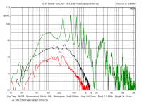
In this graph you see the unsmoothed near-field frequency response of the opening of my first test line (section: 50 cm2; length: 1m). The driver used is a Dayton Audio RS100-4. Empty line response in green, foam in black (50% filling, 14 kg/m3 total density) and fibre in red (fully filled, 16 kg/m3).
My approach to the transmission line is to maximise its potential by exploiting the low frequency contribution provided by the opening. By optimising the TL geometry, the ripple can be kept within reasonable limits.
Another approach is to overdamp the TL by filling it completely with absorbent material (in this case probably fibre is the best choice), obtaining a behaviour very similar to that of a closed box, but with better control of internal resonances. This is a viable option, but it would be a shame not to take advantage of the rear radiation of the cone, and the other properties of a well-dimensioned TL, especially if you intend to build small to medium-sized loudspeakers.
Attachments
OK thanks for that.
Your plot seems to show the attenuation from the fibre is ~7dB more than the foam up to 100Hz, increasing to 10dB by 500Hz. Doesn't that make the fibre more effective as an absorber?
My particular interest is for my current TL project using a Satori driver. I tend to target the port output to be only weakly resonant (for best transient response), which means it only augments the driver by a few dB max.
In this graph you see the unsmoothed near-field frequency response of the opening of my first test line (section: 50 cm2; length: 1m). The driver used is a Dayton Audio RS100-4. Empty line response in green, foam in black (50% filling, 14 kg/m3 total density) and fibre in red (fully filled, 16 kg/m3).
Sure looks like the red curve provides gretare attenuation and is only a level shift from the black line… something you can likely move quite close together by adjusting the densities of the foam (more) & the fibre (less).
Stuffing a line until it is aperiodic is a very useful technique at flattening the impedance curves. Particularily useful with midTLs, bass drivers with highish Q, or just the smoothest, slowest bass roll-off you can get.
dave
OK thanks for that.
Your plot seems to show the attenuation from the fibre is ~7dB more than the foam up to 100Hz, increasing to 10dB by 500Hz. Doesn't that make the fibre more effective as an absorber?
My particular interest is for my current TL project using a Satori driver. I tend to target the port output to be only weakly resonant (for best transient response), which means it only augments the driver by a few dB max.
The line is only 50% filled with foam while it is completely filled with fibre. Even under these conditions the low-pass slope is steeper with foam. What is striking is the lower amount of ripple in the foam filled TL with a low frequency contribution of 7 dB more at 100 Hz.
Last edited:
Sure looks like the red curve provides gretare attenuation and is only a level shift from the black line… something you can likely move quite close together by adjusting the densities of the foam (more) & the fibre (less).
dave
If you reduce the fibre content to reach the foam output level you will end up with an unacceptable amount of mid-frequency ripple.
If you reduce the fibre content to reach the foam output level you will end up with an unacceptable amount of mid-frequency ripple
Can you show us that> It suggests the damping characteristic is not linear.
dave
Sorry Dave, but I haven't collected any data to that effect. The graphs above refer to measurements made over a year ago during the development of the model. However, that the damping characteristic is non-linear is a well-documented fact and this applies to both foam and fibre.
- Home
- Loudspeakers
- Subwoofers
- SpicyTL - Transmission Line Simulation Model