The frequency response matches the Stasis X-air published specs, though the 38Hz 24dB crossover in the specs still makes no sense with a 30 Hz low corner.
The impedance curve suggests 6th order system, but that's a pretty wide bandwidth (30 Hz to over 200 Hz). That is a pretty decent response curve, and there are no out of band funnies either.
The impedance curves in #11 and #19 would indicate the excursion minima would be around 29 Hz, maxima around 48 Hz, so a 38 Hz HP would not be a logical excursion protection point, regardless of driver choice.@Art, To me the most logical explanation would be to protect the drivers for over excursion. We do not know what drivers are in the void and what specs they have.
Looking at the FR and impedance curves, looks more like a typographic error, HP should be 28 Hz, not 38.
103dB/1w/1m@30Hz from a :
562 mm (22.1”), Width1226 mm (48.3”), Depth 903 mm (35.6”)
(642L external volume) cab seems impressive or implausible?
The SKHORN manages around 99dB/1w/1m and is: 32 in, 24 in, 54 in (679.6L external): Data-Bass: Subwoofer Measurements
Am I making a mistake here?
562 mm (22.1”), Width1226 mm (48.3”), Depth 903 mm (35.6”)
(642L external volume) cab seems impressive or implausible?
The SKHORN manages around 99dB/1w/1m and is: 32 in, 24 in, 54 in (679.6L external): Data-Bass: Subwoofer Measurements
Am I making a mistake here?
but so is the SKHORN as far as I know.
I found this post regarding the construction:
I found this post regarding the construction:
STASY X GUESS WHAT? - Speakerplans.com Forums - Page 4Hi,
One box will hit about 30Hz in half space, thats -3dB and will be flat to around 33Hz. One Stasys X sounds the same as many Stasys X, you just pick the munber you need for the required output SPL. So for small gigs you can take out 2 and still get a useable 30 to 140Hz and for larger gigs take out loads, where you will still get 30 to 140Hz but with more SPL. The sound of the cab dosen't change when you add more either. The transient response stays roughly the same no matter how many cabs are used.
I told many at the show how Stasys X works. There are 2 18" drivers and each driver has a proper 1.6 meter horn infront of it. So thats a total of 3.2 meters of horn path. The rear chambers of the drivers are ported. But there is a difference. Each driver sits in a 22 litre rear chamber and the ports are tuned to 28Hz. if you do the calculation then you will find for the area of ports I'm using then to tune to 28Hz with an 18" driver in a 22 litre box then the ports would have to be around 4.5 meters long. Clearly the ports are not 4.5 meters long as the cabinet is around the same size as the Stasys 8, so an intermediate chamber is used between the drivers rear chamber and the ports. This uses helmholtz princibles and is a bit like blowing over a bottle neck. It fools the ports into behaving like they were tuned to 28Hz.
I was getting such a strong response down to 19Hz due to boundry effect or cabin effect. The same happens in a car at wavelengths longer than the size of the cabin. The room was big, but 19Hz has a very long wavelength, so these very low frequencies were boasted by the comparativly small size of the room at those frequences.
As I said Stasys X is good for 30Hz at -3dB when used singley or in muitiples. It was great fun being able to move a lot of the building. It was like a 32 ton truck moving past a small house and if you think of the force needed to move a small house it gives you some idea of the pressure involved. But now think that I was moving a large room and part of a massive building that has over 30 cm conreate all around it.
About the SKHORN measurement on the Data-bass page: Voltage Sensitivity
Sensitivity was measured at 14.1 volts. Corresponding to 100 watts nominal into a nominal 2ohm load. The overall sensitivity is good. We can see that the measurement at 10 meters is a bit higher than the 1 meter measurement when normalized. This is due to the separation of the acoustic radiators on the front of the cabinet face. The 1 meter measurement is a bit under-representative. Either was we see that the sensitivity is in the range of 105-107dB at 70Hz. It remains at 100dB or greater down to about 34Hz with all vents open. With only a single vent per side open it maintains a 90dB sensitivity way down at 20Hz.
Sensitivity was measured at 14.1 volts. Corresponding to 100 watts nominal into a nominal 2ohm load. The overall sensitivity is good. We can see that the measurement at 10 meters is a bit higher than the 1 meter measurement when normalized. This is due to the separation of the acoustic radiators on the front of the cabinet face. The 1 meter measurement is a bit under-representative. Either was we see that the sensitivity is in the range of 105-107dB at 70Hz. It remains at 100dB or greater down to about 34Hz with all vents open. With only a single vent per side open it maintains a 90dB sensitivity way down at 20Hz.
The frequency response matches the Stasis X-air published specs, though the 38Hz 24dB crossover in the specs still makes no sense with a 30 Hz low corner.
Those plots are for the V1 Stasys X which was a bandpass design.
Re the 38Hz high pass, I thought the same about it being strange, I think most likely a miss print and should be 28Hz.
I made some LEM sims in Akabak and must say I'm pretty confused.
BEM setup - half-space ground measurement 1m

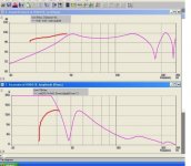
This is what I got with horn-loaded re-entrant ports going from rear chamber.


As you can see these charts are far from original stasys measurements.
However I tried to close rear ducts at the horn throat side and result is much nicer. The impedance chart almost copies the original stasys chart.


Next step is to sim the system as BEM+LEM so that in BEM will be the full geometry except the front circular ports which can be added easily as lumped elements.
BEM setup - half-space ground measurement 1m
This is what I got with horn-loaded re-entrant ports going from rear chamber.
As you can see these charts are far from original stasys measurements.
However I tried to close rear ducts at the horn throat side and result is much nicer. The impedance chart almost copies the original stasys chart.
Next step is to sim the system as BEM+LEM so that in BEM will be the full geometry except the front circular ports which can be added easily as lumped elements.

Repeating myself, the "horn loaded" ports are a lot longer than the circular ports. The longer "ports" alone would result in an Fb lower than 29Hz, the shorter ports alone much higher, mixed together they result in an Fb of 29Hz, assuming your depicted design and previously posted impedance and FR plots are from the design you are simulating.Look at the FR for various front port lengths(100-400 mm). This sim was performed with closed rear ducts.
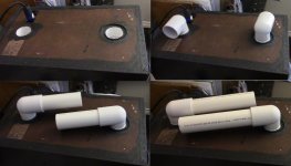
As a simpler example of mixed ports (photo below), using standard 1.5” PVC schedule 40 plumbing parts, pipe couplings for “built in” ports, then adding 90 degree slip elbows, then adding pipes from the elbows allows quick tuning changes on a pair of studio monitors/PA speakers I have been using.
Hot Rod 8” 2-Way PA/Studio Monitor
Net cabinet volume of the monitors=15.9 L or .5618 cubic feet net.
The various tunings (Fb) are roughly:
76 Hz with no elbows, both pipe coupling ports open
62 Hz with 1 elbow added to one port
60 Hz with 2 elbows added to both ports
48 Hz with two elbows and one 5" tube (past elbow)
44 Hz with elbows and two 5" tubes (past elbow)
40 Hz with elbows and one 5" and one 8" tubes (past elbow)
35 Hz with elbows and two 8" tubes (past elbow)
In each example, the addition of an extension to just one duct resulted in a lower Fb.
In the design you are considering, the VTC of the "V" horn coupling may also effectively function as a tuned resonant absorber in the "horn loaded" ports, smoothing response by reducing "pipe resonance".
Lots of interesting stuff Rog Mogale/Void incorporated in this design!
Art
Attachments
Last edited:
weltersys,
Thanks for the pictures now I understand what you mean by "the rear ports are much longer than the circular ones".
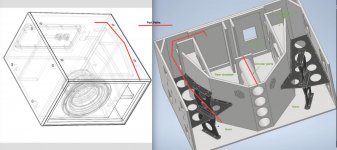
I've been modelling the system in a different way. I consider the rear ports to be just that short 3 ducts along the rear wall. The rest of the path is just folded horn.
1, 2, 3 are the rear ports
A is a duct, B, C are waveguides


Thanks for the pictures now I understand what you mean by "the rear ports are much longer than the circular ones".
I've been modelling the system in a different way. I consider the rear ports to be just that short 3 ducts along the rear wall. The rest of the path is just folded horn.
1, 2, 3 are the rear ports
A is a duct, B, C are waveguides


The ducts starting at the corner of "1,2,& 3" don't end when turning around the next corner simply because the divider/braces stop there.
"1,2,& 3", and "A, B, C" are all part of the same air column, pipe, duct, port, or horn whatever you want to call it, but a "waveguide" must be large enough to guide waves ;^).
"1,2,& 3", and "A, B, C" are all part of the same air column, pipe, duct, port, or horn whatever you want to call it, but a "waveguide" must be large enough to guide waves ;^).
") .
.
Next step is to sim the system as BEM+LEM so that in BEM will be the full geometry except the front circular ports which can be added easily as lumped elements.
Hi Maple have you tried a full Bem simulation?...
it would be interesting to analyze the propagation behavior of the waves inside the enclosure, i've tried tu set up a comsol simultion years ago whitout luck
some time ago I simulated with akabak starting from the drawings found on the net, there is a behavior in this lem simulations about the resonance at 30 hz that I cannot grasp..
the drawings on the internet will not be perfect, but certainly not to give these differences
the drawings on the internet will not be perfect, but certainly not to give these differences
Attachments
- Home
- Loudspeakers
- Subwoofers
- 2x B&C 18SW115 dual horn subwoofer