There are other threads with a similar title except no one thread really seemed to point to "who wins?"....
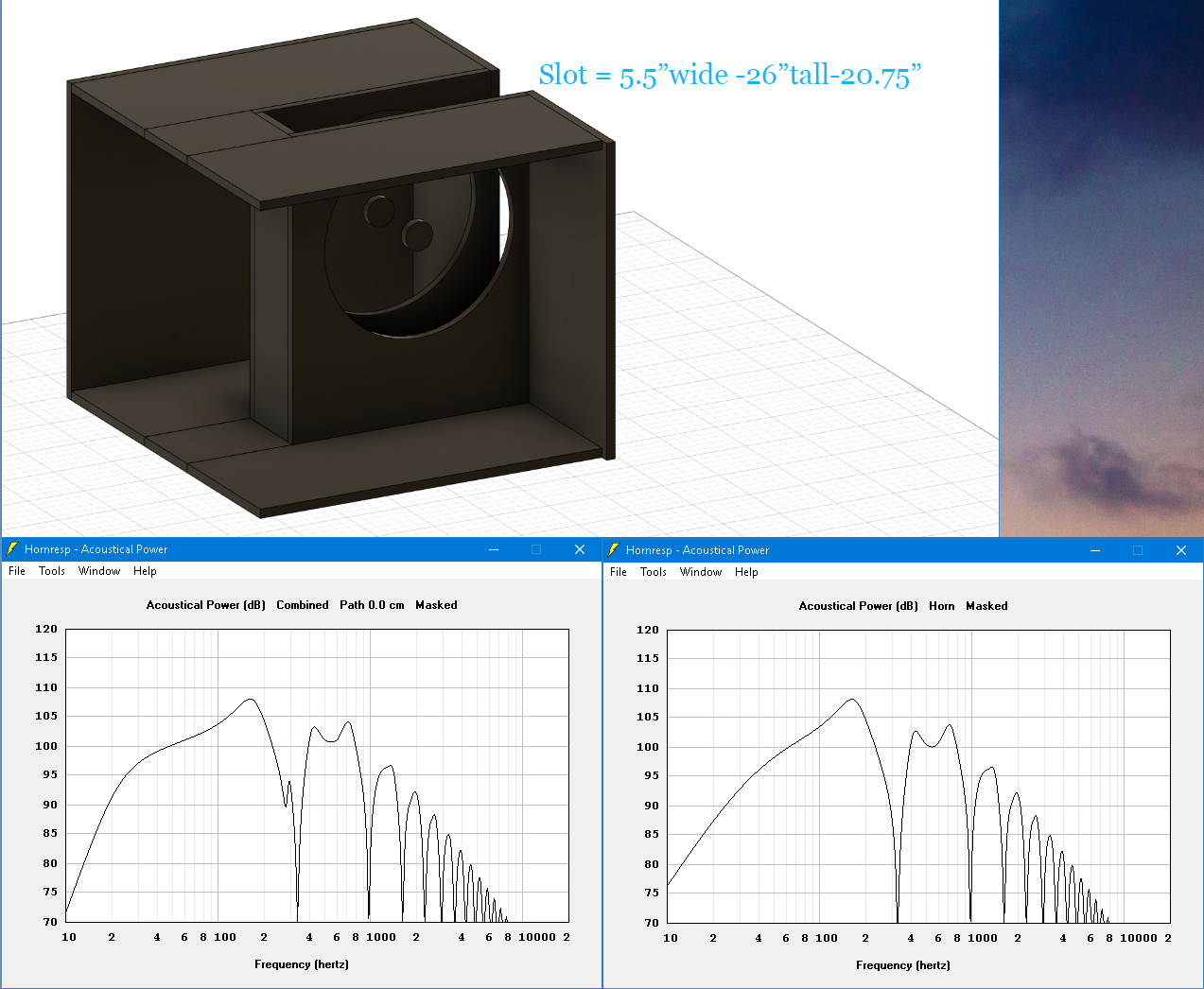
I have a sub I'm working on and I have designed it to be, sealed, Push Push in a slot...
I was ok with what I simulated until I found a better way to simulate it and with "offset horn" in HornResp and wasn't happy about the void in the FR around 300hz...that area was more efficient, as as system, with that area being usable....
Now I am questioning my logic....I have 2 pairs of 18"s....I don't have to do this push push slot load but it seems that people were really impressed with the results with the push pull slot load....
Force cancellation...dampening on the front sides of the woofer, supposed lowering of Fs.... I wouldn't have the push pull benefit for driver motion BUT the slot is tight, and the drivers should "see" each other in some type of way
Also stuck in my head...The response is going to be different than what I modelled in HornResp....
What is the best way to model this in HornResp? Can this be modelled in Akabak?
Alternatives? The focus was to try and keep the output on the front baffle between two 18's
Taking the pairs of woofers into isobaric config? Is that as step backwards?
I am really thinking that a V shaped baffle might suit better if I can regain the territory in the top register I lost in the slot
Thanks in advance for advice =)
The responses are for sealed and vented... if you are not familiar with the Fr of the AE 18H+ please don't comment on the ever increasing sensitivity lol!
Attachments

Last edited:
Camplo,1)Force cancellation...dampening on the front sides of the woofer, supposed lowering of Fs...
2)The response is going to be different than what I modelled in HornResp....
3)What is the best way to model this in HornResp?
4)Can this be modelled in Akabak?
5)Taking the pairs of woofers into isobaric config? Is that as step backwards?
6)I am really thinking that a V shaped baffle might suit better if I can regain the territory in the top register I lost in the slot
1) Force cancellation is a nice feature to prevent a light cabinet "walking". In a studio situation, adding weight can avoid that problem. The increased plenum air mass lowering Fs does effect frequency response, though the plenum "horn" effect in the upper range is larger than the LF Fs change. Fs lowers slightly in any closely paired woofers.
2) Somewhat, though room response variations will likely exceed those differences by a large margin.
3)"Offset horn" in HornResp is valid, assuming you have considered the volume of the cone cavity in addition to the plenum depth and volume.
The response dip in the FR around 300Hz won't be quite as deep or sharp as predicted, and considering the EQ needed to flatten the rest of the response, the out-of band EQ required to flatten that region of the crossover is of no concern for a "subwoofer".
4) Yes.
5) In terms of output, the isobaric pair overall loss of 6dB output would be considered a step backward for the slight increase in LF.
6) Certainly worth modeling, though for such a small cavity, the change will probably be little.
That said, having built literally tons "V" loaded dual and quad 15" bass cabinets crossed LR24 at 200 Hz, from experience can attest they work well.
Cheers,
Art
Last edited:
Thank you for laying it out for me....at 363 liters the cabinets are going to be too light...theres another cabinet (15m) going on top of the sub so theres even more weight...
SO maybe force Cancellation is not worth it for me....Is their any insight you can give me for the the V shaped baffle....am I going to so some other anomalies in the FR depending on angle? or seperation? Rule of thumbs I might abide by?
The V shape seems to be more flair like and I would imagine much smoother FR. I have to stick with 32" wide and my 32" depth as well...first I have to model it I guess...
thanks again!
Some thoughts
_I was banking on the idea that having the woofers fire into each other in the slot would somehow increase SQ? That the resistance would increase control over the cone. Is the lowering of Fs the basic manifestation of this? I could config the woofers in push pull in a V baffle....that was a warm thought lol...I envisioned some type of magical braking system in the slot? Chasing rainbows was I?The increased plenum air mass lowering Fs does effect frequency response
Last edited:
Given a fixed cabinet volume, increasing the "V" volume trades increased upper output for reduced LF output.
Judging only by the drooping LF response, your cabinet appears undersized already.
The difference between parallel or "V" baffles of such short depth will mostly be due to the plenum volume difference, and the differences likely so far above the crossover point as to be inconsequential.
If this is for a studio monitor sub, the increased 80-200 Hz response from the 18" drivers really is of little use, that range would be better covered by the mid driver to avoid localization problems.
you are mistaken, it only looks like its drooping because of the ample sensitivity climb in the upper range.Judging only by the drooping LF response, your cabinet appears undersized already.
If this is for a studio monitor sub, the increased 80-200 Hz response from the 18" drivers really is of little use, that range would be better covered by the mid driver to avoid localization problems.
is this also a problem with all other? TMM designs? The speaker that comes to mind is the JBL cinema speaker with 2 15"s crossed to a horn....Does it suffer from these localization problems too then? If not then why I wonder?
that number comes to 163hz for me and looking at the graph it makes sense.It's not recomendedo use the SLPP above a quarter wavelength of the slot depths. Use it below 100hz for best results.
Last edited:
Most decent systems using two 15"s crossed to a HF horn are 2.5 way.
That said, even in the front row of a Cinema, the angle difference between the horn and lower 15 is not much, while in your near-field monitoring system, you may have as much as a 45 degree change in source location between a floor positioned 18" and the mid/high drivers.
If the crossover between the mid and woofer is above around 100 Hz, low vocal and instrument fundamental notes will appear to "wander" up and down between them depending on their pitch.
Camplo,
1) Force cancellation is a nice feature to prevent a light cabinet "walking". In a studio situation, adding weight can avoid that problem.
Force cancelation is an elegant, active solution. Mass is brute force (and does not work as well). Besides reucing a cabinet walking, it dramaticaly reduces box vibrational loads which is even more important.
BTW: there is no winner. Results depend on the input design criteria.
dave
Another thread linked to a study Bob Katz study on loudspeaker isolation.. which basically says cabinet vibration is coupled to the building . It would be benefitical to make speakers force cancelling in that perspective as well.
I have plans on on coupling the woofers together using threaded rods even.
PLanet10 I feel like I got this from one of your post…
I'm currently working on my finish technique before I actually "finish the boxes"... Ty you guys for putting things into perspective, rather quickly....I was about to have a good amount of scrap wood, if you know what I mean...
I'm sure you are familiar with the jbl 4670...but as you said, near field vs polar....So I tried to bring the 18"s just under the crossover of the 15 to the Horn, in simulation that is....
Now I have this

PLanet10 I feel like I got this from one of your post…
I'm currently working on my finish technique before I actually "finish the boxes"... Ty you guys for putting things into perspective, rather quickly....I was about to have a good amount of scrap wood, if you know what I mean...
Most decent systems using two 15"s crossed to a HF horn are 2.5 way
I'm sure you are familiar with the jbl 4670...but as you said, near field vs polar....So I tried to bring the 18"s just under the crossover of the 15 to the Horn, in simulation that is....
Now I have this
Attachments
Last edited:
PLanet10 did ever build one of these or just make the drawing....lol....theres no way to readily manipulate the threaded rods...Im use a cap nut to drive the threaded rod and am going to have to permanently attach it to make it reversible... IM thinking jb weld or epoxy might be the trick...got any ideas?
I had to reverse a thread because I forgot to put a nut in and I snapped a threaded rod, they are aluminum because I followed the idea the same as using aluminum or SS screws for a compression driver to not mess with the magnets? (SS threaded rod is crazy expensive at 36" long)
Am I doing too much? Will the normal zinc coated steel threaded rods be acceptable?
Am I doing too much? Will the normal zinc coated steel threaded rods be acceptable?
Let me take a second to give you some praise, planet10....I've been a fan of yours since back in the parts-express days (1997 likely) you were a help then and its awesome to see you around spreading your wisdom til this day...I really appreciate it/you. Now I'm building your woofer bracing design lol, funny how things go.

Now I have this
Hmm, as drawn this is going to be literally a 'rocking' machine, vibrating back n' forth, so not a good plan.
- Home
- Loudspeakers
- Subwoofers
- Clamshell, Push-Pull Slot loaded, Alternatives....who wins?