At the frequencies involved the waveform does not see the bends.
It should also be nited that the corner deflectors i have seen in some of the drawings are counterproductive. They subtly degrade the performance of the line.
dave
It is a low pass filter, not a ‘bend’ in many respects.
Double edged sword? = a compromise? Every loudspeaker has a myriad of compromises.
A quarter-wave line sets up a series of harmonics based on its length and geometry.
If our goal is to extend the LF using the back wave we would like to preserve the fundemental resonance. But all the harmonics above that will cause ripple in the response and are unwanted. So we want to LP the output of the terminus to preserve the fundemental and supress the harmonics. Historically one would stuff the line until the 1st unwanted harmonic was suffitently suppressed. With this technique one would also end up suppressing the fundemental as well.
Post yr2k with the aid of one of the 1st modern qw-modelers that the placement of the driver would change the expression of the line’s harmonics and could be carefully placed to suppress the 1st unwanted harmonic. This means less damping can be used and more of the fundemental can be utilized.
It is also worth noting that this same modeler let us explore the effect of restricting the terminus, which adds another low pass filter to the line, further suppressing harmonics.
dave
It is a low pass filter, not a ‘bend’ in many respects.
At each bend, with no deflector, there is an expansion in the line. This expansion in the pipe cross-section does act as another low pass filter.
The reason deflectors are counter-productive.
dave
At the frequencies involved the waveform does not see the bends.
It should also be nited that the corner deflectors i have seen in some of the drawings are counterproductive. They subtly degrade the performance of the line.
dave
https://assets.thalia.media/doc/48/f4/48f486f9-15f0-4dda-ba0e-1abd2e9c20d4.pdfDoes anyone have any links to articles / other forum discussions regarding expansion in cross sectional area of line acting as LPF? This is interesting and I've never heard this before. Thanks
Looking forward to seeing this build.
this is pretty good. $50-130 on amazon its math heavy, but in between theres plenty especially if you grab a second hand or ‘slightly used price’.
Last edited:
Double edged sword? = a compromise? Every loudspeaker has a myriad of compromises.
A quarter-wave line sets up a series of harmonics based on its length and geometry.
If our goal is to extend the LF using the back wave we would like to preserve the fundemental resonance. But all the harmonics above that will cause ripple in the response and are unwanted. So we want to LP the output of the terminus to preserve the fundemental and supress the harmonics. Historically one would stuff the line until the 1st unwanted harmonic was suffitently suppressed. With this technique one would also end up suppressing the fundemental as well.
Post yr2k with the aid of one of the 1st modern qw-modelers that the placement of the driver would change the expression of the line’s harmonics and could be carefully placed to suppress the 1st unwanted harmonic. This means less damping can be used and more of the fundemental can be utilized.
It is also worth noting that this same modeler let us explore the effect of restricting the terminus, which adds another low pass filter to the line, further suppressing harmonics.
dave
2021, MJK is studying the use of ducts and chambers, not just modeling clay on a yardstick. Maybe he will find another chapter in his history as a modeler and mentor?
") or maybe we just stick a big Helmholtz on the very end of a TL end fired from that point? It sounds like a ‘roar’ to me? MJK is studying roar? kind of, I suppose? i dunno, he suggested the book to me. (Above post)
or maybe we just stick a big Helmholtz on the very end of a TL end fired from that point? It sounds like a ‘roar’ to me? MJK is studying roar? kind of, I suppose? i dunno, he suggested the book to me. (Above post)MJK’s models opened up a huge new space for speaker design. There is still lots to explore.
dave
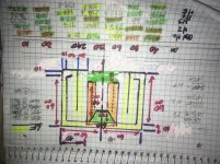
Try supporting the the harmonics we might need to work for us or against us by allowing a 71.6(40cm +80cm) hz standing wave to exist, and escape if needed. or bury them within the null in a fold that is plumbed to a pressure max elsewhere by a small pipe or tubing. we already drill holes to ambient and ducts within our Qw length shapes. the next step (some sort of) is maybe to assign them to multitask for us, and promote the responce we need, even a ‘bad’ one. Restrictor plates and orifices, skinny pipes/tunes relief pressure but do not disrupt the long wave? 240cm is a compounded horn with an 80cm rear output.. perfectly aligned in phase, minus the trip to the other.... what if thats a helmholtz and the phase results as the entire length, but only in qw on one side? helmholtz can be halfwave and/or another phase? 240cm and 120cm in a compound horn, from eother side seperate and reflected all the way from the open end of the ‘TL’ side.. Bass extension another way? a straight TL (driver entry at V max(exit), with a rear vented chamber at the same tuning, but from a higher order in length? Helmholtz will do this, but so will a halfwave
Heres an example of a design already in use(pic): Highlighted to show all of the dimensions that ‘could’ also be frequencies of each other(and the fundamebtal). Each one is an impedance null or peak or shown in phase angle as ‘x’ degrees of rotation or ‘flipped’. If we Look, its already there to see? end correction and Qlosses, a small hurdle, inductance and many details no doubt, but what's a couple cm in several hundred? Nothing, we deal with that every design and sim already as wood?
Attachments
Last edited:
Happy Holidaze and all that jive!
Yeah, was going to mention that L*0.21 is the theoretically optimal point.
It appears it's time for you to study pipe/horn musical instrument design theory. An early Karlson pipe design theory showed a pipe with spaced holes and if the holes are spaced at 1/3 octave, then based on pipe length the expo K slot flare frequency can be calculated.
Dude was no dummy and over the decades of periodically trying, still can't derive the audio equivalent of his microwave horn antenna.
GM
Yeah, was going to mention that L*0.21 is the theoretically optimal point.
It appears it's time for you to study pipe/horn musical instrument design theory
. An early Karlson pipe design theory showed a pipe with spaced holes and if the holes are spaced at 1/3 octave, then based on pipe length the expo K slot flare frequency can be calculated. Dude was no dummy and over the decades of periodically trying, still can't derive the audio equivalent of his microwave horn antenna.
GM
Does anyone have any links to articles
Scroll down to III A: http://users.cms.caltech.edu/~ps/All.pdf
GM
Build #1
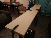
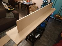
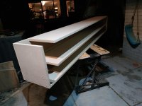
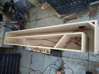
Hey guys, build has started!
As I don't have a workshop and outside is 'dutch weather' I did some work in the living room.
First I clamp the pieces for predrilling and screwing. If all fits well I unscrew, add wood glue and screw again. I use only little screws (big ones can screw up MDF, you know), max 20cm between, just as clamps for the glue to dry. I have some big clamps, but not enough for this big project.
Right now, half of the parts is glued.
Attachments
Last edited:
Thanks GM

Happy Holidaze and all that jive!
Yeah, was going to mention that L*0.21 is the theoretically optimal point.
It appears it's time for you to study pipe/horn musical instrument design theory
Dude was no dummy and over the decades of periodically trying, still can't derive the audio equivalent of his microwave horn antenna.
GM
Im digging more rabbit holes and for sure need to look at apertures and splayed drivers soon! right now im 10 harmonics deep
oI use this (link) for fast reference to stubs, folds and offsets. still trying to ‘perfect’ a extended roar/paraflex in phase at the ‘middle’. as soon as there's a ‘tapped entry or an offset From a closed/exit end things get wacked and theres no ‘perfect’ to be found. A 120 cm offset driver followed by 200cm TL or any combo of 120/fold/120 and rear vented 80cm is great. seems im chasing pythagoreum in layout(?), meanwhile sprinkling segmental CSA bumps at folds to LP filter along the way and stretch out the response shape where appropriate.
60 degrees in compound or 90 degrees in standard qw pipes @ exit/direct radiator is pretty easy in a straight CSA based on Vas and Qts, but anything else in the pipe, or segments of it, gets mentally un forgiving fast
Resonances of open air columns
Looks great PCSoldaat !
Are you lining the internals?
I will put some foam in the bottom and first fold. Some stuffing in the bottom. Just al little.
Stuff the heck outta the bottom(behind/upstream of the driver area), its not impeeding ‘travel’ to exit of the wave of interest, it can become more of a helpful area if stuffed, its not harming anything. its just not very affective at pressure max/velocity Min(the very bottom). Its s free zone created by offset so might as well stuff it. Kind of like corners in turns, they are already a mini ‘offset’ point(or two of them in a 180 degree fold) so might as well take advantage of the fact and stuff them. The outside radius is ‘faster’ and affectively more potent in a turn too. low pass filter with stuffing can be even better low pass, standing waves can be neutered or promoted. As Dave pointed out, the fundamental is typically all you want at exit.
I agree re putting more lining in. In my bass reflex build, i read so many articles on whether to line or not, and opted for none to maximise the efficiency. Upon listening, the box had a sound, although almost insignificant, I couldn't live with it. I put lining in retrospectively but was unable to line the slot port - unable to access once built. My measurements for before/after lining the main enclosure volume are here, well worth it IMO - Project – 2 x Peerless XLS 10” 20Hz tuned slot port subwoofer
This build will be awesome, even with a little lining.
This build will be awesome, even with a little lining.
Last edited:
Build #2
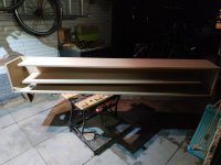
Update!
Few pics of last days:
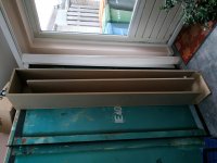
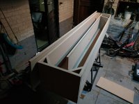
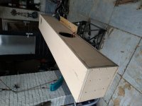
For comparison how tall this sub is. Taller than my door.
Finished all the panels.
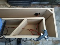
Today the interesting stuff:
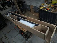
I put in the wiring. At the bottom of the line I made a little compartment. Won't use it now, but maybe later I can add a crossover in it. The wire is fixed with hotsnot.
At the driver I attached the wire to the inner panel. For in case it drops to the bottom....
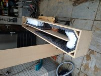
Then the stuffing. I filled the bottom and a little at the bend.
Final shot of the inside. Will miss the view, somehow
OK, case is closed and glued. Time to add the driver, while the manager is watching
No time for a proper test, but wow I am impressed! Even at a little power the windows shake in the whole house; says my wife.
But the smoothness impresses me the most. It feels like it's too easy to drop the bass. Love it.
Update!
Few pics of last days:
For comparison how tall this sub is. Taller than my door.
Finished all the panels.
Today the interesting stuff:
I put in the wiring. At the bottom of the line I made a little compartment. Won't use it now, but maybe later I can add a crossover in it. The wire is fixed with hotsnot.
At the driver I attached the wire to the inner panel. For in case it drops to the bottom....
Then the stuffing. I filled the bottom and a little at the bend.
Final shot of the inside. Will miss the view, somehow
OK, case is closed and glued. Time to add the driver, while the manager is watching
No time for a proper test, but wow I am impressed! Even at a little power the windows shake in the whole house; says my wife
.But the smoothness impresses me the most. It feels like it's too easy to drop the bass. Love it.
Attachments
-
 IMG_20201226_144949.jpg662.5 KB · Views: 204
 -
 IMG_20201226_175606.jpg647.5 KB · Views: 75
 -
 IMG_20201228_114409.jpg943.8 KB · Views: 81
 -
 IMG_20201228_115047.jpg983.7 KB · Views: 91
 -
 IMG_20201228_125021.jpg826.3 KB · Views: 99
 -
 IMG_20201228_151551.jpg995.9 KB · Views: 112
 -
 IMG_20201228_153744.jpg859.6 KB · Views: 96
 -
 IMG-20201228-WA0003.jpg155.4 KB · Views: 113
- Home
- Loudspeakers
- Subwoofers
- Which 10" driver for 4m TL?