Yes, it protects others from your (expletive deleted) screams when the edge of the heavy ceramic magnets crush or cut your fingers when you loose your grip.There is a big rubber band around the magnet. Does it have an acoustic function?
Contrary to GM's observation, (the 900 series ceramic magnets weighed over twice as much as the Alnico magnets which it replaced when Cobalt became Unobtanium) rubber bumpers are added for cosmetic reasons, and to protect the hard edge of the magnet from chipping- those chips can cut like a (ceramic) knife. You won't see rubber bumpers on smooth cast Alnico or Neo magnet structures.
I've removed loads of rubber bumpers from LAB12 woofers, they have enough trouble getting rid of heat without putting an insulator around the magnet ;^)
Last edited:

Great choice on the drivers! IMO, they are the best looking subwoofer drivers out there, thick black surround which represents the drivers excursion capabilities and smart inverted aluminium cone. Some photos of the front of the driver would be nice! Haha!
I plan on buying two to replace the two 10" peerless drivers in my ported design.
I plan on buying two to replace the two 10" peerless drivers in my ported design.
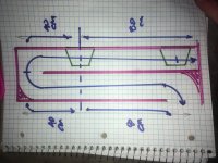
‘Path’ is clearly half of the vertical height in both based on the pictures. You are leaving 100cm if acoustically significant whiskey in the bottle. but in a side note, they look awesome and i bet they are even better in person asthetically! I dont know of i would tune a 25 hz driver with 0.5 qts to 15, but maybe under low power or ?
Last edited:
Driver location does not impact line length. Only the structure of the generated quarter-wave resonances.
dave
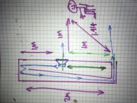
Sorry for the silly pic, but this always gets kindof diluted or confusing to many people i think? Im in the group

Attachments
Last edited:
Driver location does not impact line length. Only the structure of the generated quarter-wave resonances.
dave
I don't follow; I mean I normally base a [ML]TL's layout on what the seated ear height or whatever location from the floor someone wants, then line length is based on this plus desired driver offset in the line, so to me it definitely impacts practical path-length.
GM
Sorry for the silly pic, but this always gets kindof diluted or confusing to many people i think? Im in the group
Nice drawing Booger!
I got your point. In fact, my sub will be in a corner and we sit on a distance. Plus there will be a lot of reflections against floor, wall and ceiling.
Thanks for all help guys. As with all of my projects; design and build have an overlap
I already had a plan to shorten the length a little by adding a second bottom and give it an angle to reduce standing waves. Maybe I will fill this lost space with some mass. If I can handle it
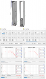
So my line is 4.0 m and the driver is at 1.0 m.
There will be some filling, but not too much. My amp with lowpass will remove the midrange anyway.
At 125 Watts (which I won't use) the displacement and breathing looks healthy.
I already had a plan to shorten the length a little by adding a second bottom and give it an angle to reduce standing waves. Maybe I will fill this lost space with some mass. If I can handle it
So my line is 4.0 m and the driver is at 1.0 m.
There will be some filling, but not too much. My amp with lowpass will remove the midrange anyway.
At 125 Watts (which I won't use) the displacement and breathing looks healthy.
Attachments
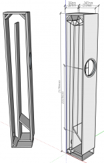
i gotta throw a ‘turd in the punchbowl’
Not exactly sure if this likely to overexcite the line from the Fb/3 harmonic down? or short circuit wavelengths to that qw length from the start/first driver?
( i liked your tall cab so much PCSoldat, i have 2 peerless 6.5s to get to the mid 30s. Thought about this in the past, never ‘splayed out drivers so far though)?)..
Attachments
Last edited:
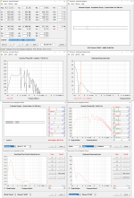
It does not matter what the Zd is the length of the line remains the same. Moving the Zd around affects how the harmonics train appears. Ideal Zd will almost completely suppress the 1st unwanted harmonic in the line.
dave
How about a two fold pipe. One at 200cm and the driver entry at another fold at 100cm within a 300cm line?
At the frequencies involved the waveform does not see the bends.
It should also be nited that the corner deflectors i have seen in some of the drawings are counterproductive. They subtly degrade the performance of the line.
dave
Kindof a Double edged sword if intending to use that harmonic, or trap it. 80,40,40,80 is all part of 240cm Fb...
- Home
- Loudspeakers
- Subwoofers
- Which 10" driver for 4m TL?