Hornresp takes into account the solid angle into which the H-Frame or U-Frame system radiates.
Yes, I supposed you did have a working simulation of the basic driver mounting.
The simulation model is valid at those frequencies where the dimensions of the system and the distance from the wall or walls are small compared to the wavelength, and where the system radiates symmetrically into the solid angle.....
Yes, that sounds dandy until somebody asks, "Hmmm, I wonder what distances from the wall he's talking about?".*
From what you say ("small compared to..."), it seems to me, the answer is that your model loses validity around 3 inches from the wall for the treble and somewhere beyond a foot or two for most of the rest.
Please correct me if wrong. Anybody have measurements - which ought to take about 5 minutes to simply move your dipole more or less distance to the back wall?
B.
* Are there problems with your simulation for the other kinds of cabs when they have much depth, even if pushed back to the wall?
Last edited:
the answer is that your model loses validity around 3 inches from the wall for the treble and somewhere beyond a foot or two for most of the rest.
How have you determined the distance limits?
Are there problems with your simulation for the other kinds of cabs when they have much depth, even if pushed back to the wall?
Not that I am aware of.
How have you determined the distance limits?
I didn't determine the distance from the wall where your model breaks down. You posted it. You wrote (rather vaguely):
"The simulation model is valid at those frequencies where the dimensions of the system and the distance from the wall or walls are small compared to the wavelength, and where the system radiates symmetrically into the solid angle."
Dipole are (1) always set a non-negligible distance from the wall behind and (2) almost inevitably at some kind of toe-in angle regarding the rear and side walls of the room. (And also the rear of a dipole might well be facing a complex absorbing and reflecting wall, unlike cabs with no rear wave.)
So how are you instructing dipole designers to use your app light of these departures from your foundational assumptions?
B.
I didn't determine the distance from the wall where your model breaks down. You posted it. You wrote (rather vaguely):
"small compared to the wavelength" is the expression used in every acoustics reference text book that I have read.
For example, to quote from Harry Olson's classic "Acoustical Engineering" book:
"Of course, as pointed out above, these examples hold only when the dimensions of the radiator and the distance from the wall are small compared to the wavelength."
When you gave specific distances, I was hoping that perhaps you had further information / knowledge on the subject that I was lacking.
So how are you instructing dipole designers to use your app light of these departures from your foundational assumptions?
I don't instruct people to do anything - they can use Hornresp any way that they like.
The only reason that I posted to this thread originally is because 'audfrknaveen' asked for assistance in designing a H-frame subwoofer, and I thought that perhaps Hornresp could help in this regard. The upper limit specified was 100 hertz. I have no practical experience with dipole systems, but I am surprised that the precise positioning relative to any walls is such an issue at bass frequencies.
Incidentally, the dipole model used in Hornresp was developed by diyAudio poster 'bolserst' (who would have to be one of the smartest people I know). He has validated the model predictions against actual measurements.
Last edited:
"small compared to the wavelength" is the expression used in every acoustics reference text book that I have read.
For example, to quote from Harry Olson's classic "Acoustical Engineering" book:
"Of course, as pointed out above, these examples hold only when the dimensions of the radiator and the distance from the wall are small compared to the wavelength."
When you gave specific distances, I was hoping that perhaps you had further information / knowledge on the subject that I was lacking.
Can you put a ballpark figure on it?
Can you put a ballpark figure on it?
Not really, your guess is as good as mine...
If I was forced to pick a value I would probably settle on a distance somewhere around one-quarter of a wavelength, which would be 86 cm at 100 hertz (assuming a sound velocity of 344 metres per second).
...If I was forced to pick a value I would probably settle on a distance somewhere around one-quarter of a wavelength, which would be 86 cm at 100 hertz...
OK, we have a number to work with. Thanks for your courage to offer it and for scottjoplin's perseverance in asking for it.
So if you have an OB that is 34 inches or more from the wall (aren't they all?), when you look at the simulation plot, the whole part north of 100 Hz is wrong to some degree and worser higher you go? Ditto for an OB up close to the wall at 17 inches for the whole plot over 500 Hz?
Of course, there's nothing wrong with the OB - they sound great despite having a nature that is hard to pre-simulate. Modelling also falls short in terms of angle to the back wall, radiation from the rear of a driver, and the acoustic properties of the wall (or window) back there and ambient everywhere else.
All together, that means you have to have your DSP ready to EQ the tone once you carry your new OBs into your music room (north of 100 Hz only) and not to believe everything will be fine when you start the music because you think your engineering was so totally well thought out.
B.
So if you have an OB that is 34 inches or more from the wall
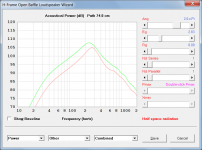
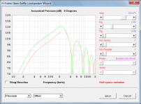
In that case, assuming that the H-Frame or U-Frame baffle is still sitting on the floor, I would probably just play it safe, take a conservative approach, and specify Ang = 2.0 x Pi rather than Ang =1.0 x Pi for the simulation. The actual performance would hopefully lie somewhere between the predicted results for the two settings, but I don't really know. As I have said before, I have no practical experience in such matters.
In the attachments, the green trace is the quarter space response and the red trace is the half space response. I would expect the actual performance to be somewhere between the two, probably biassed somewhat towards the green trace.
All together, that means you have to have your DSP ready to EQ the tone once you carry your new OBs into your music room (north of 100 Hz only) and not to believe everything will be fine when you start the music because you think your engineering was so totally well thought out.
Exactly, and of course that really applies to any loudspeaker installed in an enclosed space, not just to H-Frame or U-Frame types. Most speakers are normally simulated as point sources radiating into a given solid angle and most commercial products are usually tested in anechoic chambers, so actual performance will obviously be affected any time that those ideal conditions are not met.
Attachments
Adding a bit to what DMcBean and Bentoronto have been discussing:
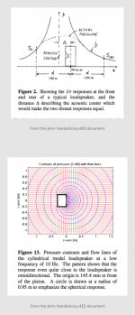
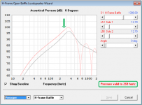
At low frequencies where the piston/baffle sizes are small compared to the wavelength, H-frame/U-frame/flat-baffle woofers can be modeled as a set of two point sources. The separation distance between the sources is defined by the acoustic center theory mentioned in Post#17. A few figures from the AES papers, shown in Attachment #1, illustrate that at low frequencies the point sources should not be positioned at the driver cone or H-frame opening but rather a distance in front. The distance to the acoustic center is mainly defined by the size of the baffle, but is also affected by the size of the driver, and the depth of the cabinet. Accurate definition of the separation distance is important since the acoustic output at LF is directly dependent on it. The predicted response is accurate as long as the sources continue to behave as point sources. In general, acoustic theory sets the threshold as ka=1, or when the wavelength of sound is similar in size to the circumference of the radiator or baffle. Hornresp identifies this threshold for the user both numerically, and by bold/light transition in the response curves.(see Attachment #2)
At its core, Hornresp is a power response modeling tool. For both dipoles and monopoles, it calculates the total acoustic power radiated(not just on-axis) into the radiation space the user selects; sphere/hemi-sphere, etc. This being the case, the LF power response curves give you a good representation of what the average room response will be so you can use them to predict/compare LF energy levels. This is the key benefit of the Hornresp model; that you can accurately compare the LF power radiated into the room by a dipole with that from the more familiar monopole subwoofer. Both the monopole(single point source) and dipole(two point sources) will energize the room with their net radiated acoustic energy and you will see peaks and dips from room modes superimposed on the power response curve based on woofer and listener locations and proximity to each other. Some years ago there was an interchange between geddlee and John K. on the topic. They started out with quite different ideas on how monopole/dipole/cardiod woofers interacted with a room, but eventually they reconciled on most points. Here is a link I had saved to a key post at the latter end of the thread. Cardioid Bass
REW includes a room simulator allowing experimentation with placement of point sources and listening positions in rectangular rooms that may be of interest.
Room Simulator
Attachments
Last edited:
With that background, here are a few more details on the H-frame model and some comparisons with measurements from last year.
Two pieces of information are needed for the two-point source model of an H-frame woofer:
- the frequency response of each of source
- the separation distance between them
The magnitude/phase response of each source is defined by the woofer parameters, the size/shape of any tunnels in front/behind the woofers, and the radiation impedance loading the tunnels and/or woofer. For symmetric H-frames, the two sources will have response with equal magnitude but 180deg difference in phase. If the H-frame is asymmetric, or damping is added to one of the tunnels the source responses will be different. Note that both the radiation impedance and the acoustic center locations are a function of the radiation space.
Here are some example measurements of an SLS-12 woofer mounted in a symmetric H-frame baffle.
Attachment #1: A comparison of the near field response for one side of the H-frame was used to evaluate the Hornresp radiation impedance model for 3 commonly used radiation spaces. 4-Pi measurement was with H-frame on a pole stand in middle of garage. 2-Pi was with H-frame on the floor. 1-Pi was with H-frame on floor up against one wall. Hornresp can accurately calculate the near field response of the dipole sources for all 3 placements in the room.
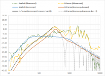
Attachment #2: For evaluating the accuracy of the acoustic center locations, measurements were taken of the same SLS-12 woofer in a sealed enclosure and H-frame at a distance of 2m outdoors in the driveway. Although wind was causing more LF noise than I would have liked, you can clearly see that the level of the LF pressure response calculated by Hornresp for the H-frame lines up well with the measurements relative to the sealed enclosure response. This indicates that the calculated acoustic center locations are correct. It also looks like ka=1 is a reasonable cut-off point for where the sources stop behaving like point sources and directivity due to source size ramps up.
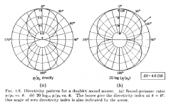
Attachment #3: Note that the power response for the H-frame in Attachment #2 is roughly 4.8dB below the measured on-axis pressure response. This is because of the DI (Directivity Index) inherent in dipole sources. In other words, a dipole source will measure 4.8dB louder on-axis than a monopole source of the same strength. Or conversely, for the same on-axis SPL level, a dipole source radiates less total acoustic energy into the room than a monopole.
Two pieces of information are needed for the two-point source model of an H-frame woofer:
- the frequency response of each of source
- the separation distance between them
The magnitude/phase response of each source is defined by the woofer parameters, the size/shape of any tunnels in front/behind the woofers, and the radiation impedance loading the tunnels and/or woofer. For symmetric H-frames, the two sources will have response with equal magnitude but 180deg difference in phase. If the H-frame is asymmetric, or damping is added to one of the tunnels the source responses will be different. Note that both the radiation impedance and the acoustic center locations are a function of the radiation space.
Here are some example measurements of an SLS-12 woofer mounted in a symmetric H-frame baffle.
Attachment #1: A comparison of the near field response for one side of the H-frame was used to evaluate the Hornresp radiation impedance model for 3 commonly used radiation spaces. 4-Pi measurement was with H-frame on a pole stand in middle of garage. 2-Pi was with H-frame on the floor. 1-Pi was with H-frame on floor up against one wall. Hornresp can accurately calculate the near field response of the dipole sources for all 3 placements in the room.
Attachment #2: For evaluating the accuracy of the acoustic center locations, measurements were taken of the same SLS-12 woofer in a sealed enclosure and H-frame at a distance of 2m outdoors in the driveway. Although wind was causing more LF noise than I would have liked, you can clearly see that the level of the LF pressure response calculated by Hornresp for the H-frame lines up well with the measurements relative to the sealed enclosure response. This indicates that the calculated acoustic center locations are correct. It also looks like ka=1 is a reasonable cut-off point for where the sources stop behaving like point sources and directivity due to source size ramps up.
Attachment #3: Note that the power response for the H-frame in Attachment #2 is roughly 4.8dB below the measured on-axis pressure response. This is because of the DI (Directivity Index) inherent in dipole sources. In other words, a dipole source will measure 4.8dB louder on-axis than a monopole source of the same strength. Or conversely, for the same on-axis SPL level, a dipole source radiates less total acoustic energy into the room than a monopole.
Attachments
I wonder if you, bolserst, or David, can comment on the method I have been using for generating the free-field response of a dipole (e.g. H-frame). I first build it and then install the driver. I then take nearfield measurements at the front and rear, in the plane of the mouth of the H-frame tunnel. Next I import these responses as FRD files into a program for crossover modeling. For the rear response, I make sure that the phase is inverted (this may or may not be captured in the measurement depending on what type of phase response was saved). Then I delay the rear by some amount of time that represent how long it takes for sound to travel the front-to-rear pathlength difference. Finally I reduce the gain of the rear sound by the ratio of the distances of each source (the front and rear mouth openings) to the listening position for which I am generating the free field response. Finally, I add the two responses (these are complex quantities) and get the sum (magnitude, which is converted to SPL). I take this as the free field response at the position that I am simulating.
I like this approach because the measurements capture the tunnel resonances, which I don't like to model. It also correctly captures the driver's response when mounted in the H-frame, where it will experience some extra loading from the air mass in the tunnel. This can influence the F and Q of its response compared to e.g. free air.
This requires me to build the enclosure and take measurements and cannot be used to do a priori modeling. But it is enough for me to get data that I can then use as part of the system crossover design and I do not need to go outdoors to make the measurements so I can do it anytime.
Any thoughts on that approach?
Adding a bit to what DMcBean and Bentoronto have been discussing:
Many thanks bolserst, a very valuable and interesting contribution to the discussion!
I wonder if you, bolserst, or David, can comment on the method I have been using for generating the free-field response of a dipole (e.g. H-frame).
Hi Charlie,
Definitely one for bolserst
") .
.Kind regards,
David
A couple questions:… can comment on the method I have been using for generating the free-field response of a dipole (e.g. H-frame)….This requires me to build the enclosure and take measurements and cannot be used to do a priori modeling. But it is enough for me to get data that I can then use as part of the system crossover design and I do not need to go outdoors to make the measurements so I can do it anytime.
- How high in frequency are you using the response?
- How are you determining relative level compared to the rest of the loudspeaker when designing the crossover?
Perhaps it is a fully active system where you simply use DSP LP crossover and adjust level to taste?
As long as you are crossing over below ka=1 where the two sides of the H-frame are still behaving like point sources, your method will give you results that should match what you measure outside quite closely. Even the path difference you use will have only minor effect on the response shape below ka=1…only changing the level. As you approach ka=1, path difference selection will start having more and more effect on the response.
If it is important to have more accurate response above ka=1 where directivity of the H-frame sources is coming into play, you might consider using an approach similar to what JohnK recommended many years ago. Basically do the combined NF approach like you are currently doing, but supplement it with far-field measurement of the H-frame using a measurement window long enough that you can splice it in at ka=1. I would think an indoor ground plane measurement with mike 1-2m away should give you what you need. Later this weekend, I will have access to the data used for the outdoor example I posted and can use it to compare this splice approach with the "full-up" outdoor measurement.
Attachments
I use this approach for H-frame subwoofers only. Therefore I do not need to have an accurate picture of the FR above, say, 200Hz. This nearfield-only method is not accurate for higher frequencies, of course.A couple questions:
- How high in frequency are you using the response?
- How are you determining relative level compared to the rest of the loudspeaker when designing the crossover?
Perhaps it is a fully active system where you simply use DSP LP crossover and adjust level to taste?
Because I am generating the "free-field" (4Pi) response I usually have to adjust the level down by 3dB or so to match the rest of the system. I do that by ear, along with other minor tweaks to the crossover, after I have developed and implemented it, as a final "tuning". Also, one may want an elevated bass response (or not) and so I feel this can be left as an adjustable parameter to some extent. Yes, I use DSP and its a fully active system, so I can do this ad nauseum (but hope not to!).
As long as you are crossing over below ka=1 where the two sides of the H-frame are still behaving like point sources, your method will give you results that should match what you measure outside quite closely. Even the path difference you use will have only minor effect on the response shape below ka=1…only changing the level. As you approach ka=1, path difference selection will start having more and more effect on the response.
If it is important to have more accurate response above ka=1 where directivity of the H-frame sources is coming into play, you might consider using an approach similar to what JohnK recommended many years ago. Basically do the combined NF approach like you are currently doing, but supplement it with far-field measurement of the H-frame using a measurement window long enough that you can splice it in at ka=1. I would think an indoor ground plane measurement with mike 1-2m away should give you what you need. Later this weekend, I will have access to the data used for the outdoor example I posted and can use it to compare this splice approach with the "full-up" outdoor measurement.
Right, I am basically following Kreskovsky's method, but do not do the far field measurement for higher frequencies because they are out of band and I don't need that information. He described the method here:
measure a dipole
He uses the front mouth response also for the rear, but I actually measure the rear because it is often slightly different on account of the magnet/basket and minor position differences within the H-frame, or when using a U-frame.
Last edited:
In terms of theory and technicalities, there is so much knowledge being shared in this thread, and I'm very thankful to everyone here !!!
I made the h frame (please see the attached image)
But I have to wait for a few days before I test it.
I'm occupied with some other activities.
Hopefully I will update listening impressions soon.
Once again thanks a lot guys
Regards,
Audfrknaveen
I made the h frame (please see the attached image)
But I have to wait for a few days before I test it.
I'm occupied with some other activities.
Hopefully I will update listening impressions soon.
Once again thanks a lot guys
Regards,
Audfrknaveen
Attachments

If your interest lie solely in response < 200Hz (which would fit the ka<1 threshold for all but the largest H-frames) then your method will give accurate response for use in crossover modeling. The accuracy of the SPL level will still be dependent on exactly where you take the NF measurements, and what source separation distance you use in your delay calculations. But as long you are setup to be able to easily adjust level up or down as needed, I wouldn’t think you need to fret too much about the exact value. I’m not sure what you use for separation distance, but the Linkwitz recommendation for Hframes [ d1 + d2 + 2*(w/2) ] is a good rule of thumb that is reasonably close to the results of the acoustic center calculations.I use this approach for H-frame subwoofers only. Therefore I do not need to have an accurate picture of the FR above, say, 200Hz. This nearfield-only method is not accurate for higher frequencies, of course…I actually measure the rear because it is often slightly different on account of the magnet/basket and minor position differences within the H-frame, or when using a U-frame.
Attachments
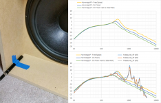
It's a Fi Audio IB318v2. I built the structure from butcherblock (the sides) and granite slabs (the top) to provide mass. The sub is not in use now - its in a corner with a lot of stuff piled on top of it. I will try to get a pic of it and post it later.
Here is the driver:
IB3 Series - IB318 v2 | Fi Car Audio
This driver is not expensive (in the USA at least) and has specs that are perfect for dipole (e.g. H-frame) sub use. Distortion is not the lowest, but remains below 10% at low frequency and not too high SPL (I measured it once).
Sub sounds great in use, solid down to the upper 20s. Because of the length of the H-frame the dipole losses are not all that bad. I'm not a bass fanatic and it is not going to break windows, etc. but sounds very good to me. It's in a room measuring about 15 feet wide and 35-40 feet long (in a finished basement).
- Home
- Loudspeakers
- Subwoofers
- Help to design H frame subwoofer