Look at the graphs in the last pages of MJK´s paper that you attached.Dear David its fantastic to see that graphs !!! Thanks a lot for making this thread more informative !! Im sure it helps a lot of people.
But there is always a peak.
How should I design a compact H frame or U frame to get a Flat frequency graph approximately 100hz to 40hz if that's possible. Assuming the room is 12x15ft and the driver is PRV15W1000V2 with Fs 40hz, Qts 0.68 and Xmax 6mm
You will see a rising response as well.
Ultimately you´ll get a flat response when you apply a low pass.
I´d suggest that you try some simulation software to see how you could filter your h-frame subwoofer and what it does to the response and read some more theory on MJK´s site or here:
Dipolplus - Alles über offene Schallwände
I like Tolvan´s free "basta" simulation-SW as it is quite an allround package with baffle/-simulation (a h-frame woofer would have to be "unfolded" in order to model it), active/passive filters, ts-parameter, approximation of room gain etc.
How should I design a compact H frame or U frame to get a Flat frequency graph approximately 100hz to 40hz if that's possible.
H-frame and U-frame open baffle loudspeakers are acoustic dipole systems, meaning that bass performance will be significantly compromised no matter what. I would be very surprised if it was possible to achieve a flat frequency response between 40 Hz and 100 Hz, and even more so in the case of your proposed compact system.
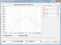
Be careful when comparing Hornresp results to those produced by other simulation software, as sometimes only the response from one side of the diaphragm is given, which can be very misleading indeed. To illustrate, the green trace in the attachment shows the output from one side of your H-frame system design. The red trace shows the total system output.
Furthermore, measurements are often done with the microphone close to one output only, which can also lead to an inaccurate assessment of overall bass performance.
Perhaps it is time to download a copy of Hornresp, and try experimenting for yourself? By far the best way to learn, is by doing...
") .
.Attachments
a h-frame woofer would have to be "unfolded" in order to model it
"Unfolding" the H-frame baffle would change the acoustical impedance loading on the diaphragm, making any simulation results inaccurate.
"Unfolding" the H-frame baffle would change the acoustical impedance loading on the diaphragm, making any simulation results inaccurate.
But isn't the acoustical impedance (air mass) difference a very small factor in an otherwise large and soft simulation of an otherwise barely simulatable situation as per my earlier screed about textbooks.
Might be other small differences that are hardly worth losing sleep over such as diffraction from a narrow H compared to a broad flat panel simulation.
B.
How should I design a compact H frame or U frame to get a Flat frequency graph approximately 100hz to 40hz if that's possible.
The short answer is: you can't get that kind of flat response. Dipole systems require equalization to be "flat".
The long answer:
You might want to go back and read my post earlier in this thread again. There will be two responses that add together to makeup the output of the H-frame:
- The response of the H-frame itself, when modeled with a hypothetical driver having infinitely wide (e.g. extending to DC) frequency response
- The response of the driver in free air
- To a first approximation, by adding these two responses together you will get the response of the driver in the H-frame.
Martin King used a high Qts woofer, the Alpha-15A. Qts is something like 1.2 or so. So this driver is flat or even has a slight peak above Fs before its eventual LF rolloff. Any peaking will help to make up for the rolloff that comes from the H-frame response, which will be at 6dB/octave. But that will only help in the vicinity of the peak, e.g. around the free air Fs. The rest of the sloping H-frame response remains, and there is no way to flatten it with a driver. You will need to apply some kind of "frequency shaping" like EQ via DSP or active filters. A passive shaping circuit at such low frequencies will require a very large and expensive inductor, so I don't recommend that approach. Martin King carefully (or serendipitously) chose the size of the H-frame opening so that the dipole peak was easily combined with a low-pass filter to flatten the response. You cannot do this with just any size H-frame, the aspect ratio has to be just right so that the H-frame response and the filter combine to result in a flattened passband.
What about other drivers in an H-frame?
"Normal" subwoofers drivers will have a lower Qts, e.g. below 0.5. IF you plot the response of the driver in an infinitely sized closed box (this is like the free air infinite baffle response) you will see how the driver's own response droops at low frequencies. This would add to the drooping response of the H-frame and make it even worse. It is possible to EQ that up to be relatively flat, hwoever, that can require HUGE amounts of input power depending on just how much loss you need to make up. HUGE means 1kW or more, of course depending on how much boost you need to apply. You will not be able to get a flat response from this kind of driver using the Martin King approach because the LF end will be drooping and the LP filter does not do anything there.
What about the H-frame itself:
The smaller/shorter you make the H-frame the higher in frequency is the point where the dipole losses begin, e.g. the 6dB sloping down to lower frequencies. By making the H-frame small, you are building in more losses and insuring that your 40Hz to 100Hz band is located in the downsloping portion. In fact, by 100Hz already there might be 6dB of output loss compared to a closed box if you make the H-frame only 16" deep, or 8" on each side (you mentioned that size earlier). There is no "magic" to this - you must make the H-frame longer in order to prevent the dipole cancellation losses from being too high.
How can I model the H-frame response?
You will need a program that can model the effect of the "Tunnels" of the H-frame, e.g. the resonances they will create. I think HornResponse can do it. I don't bother to model it. Instead, based on my knowledge of what should happen, I just build a very flimsy version of the H-frame I wish to build (e.g. using 6mm pressed wood panels), install the driver, and then measure the response at the front and rear mouth planes. The measurement data captures the tunnel resonances, and the driver response, but does not include the interaction of the front and rear waves that forms the dipole pattern in the far field. So you have to model that. But it is easy. You use a program that can import the FRD files, make sure the phase of the rear wave is inverted, and then add the two like they are point sources (valid at low frequencies). I can tell you more about it if you would like. The resulting data is what you will observe or measure in open space for the real H-frame.
Honestly I think it has more to do with loading the cone with an additional air mass (trapped in the H-frame's front and rear tunnels) than an acoustical impedance change, but you can indeed measure changes in driver Fs and Qts when mounted in a deep H-frame that are non-negligible.But isn't the acoustical impedance (air mass) difference a very small factor...
Might be other small differences that are hardly worth losing sleep over such as diffraction from a narrow H compared to a broad flat panel simulation.
RE diffraction from the H-frame opening, that is probably not worth worrying about. At very low frequencies there will not be appreciable diffraction effects. At frequencies high enough to matter, you are not using the H-frame there (e.g. >500Hz) so they would be inconsequential.
Thanks for the correction."Unfolding" the H-frame baffle would change the acoustical impedance loading on the diaphragm, making any simulation results inaccurate.
I´m pretty sure that MJK´s sheets, hornresp and a few other programs to a much more precise job of modelling a h-frame.
Most programs miss a thing or two and make "assumptions" as I know of.
Details like floor-bounce and others are not modelled in each and every program.
Nevertheless it might be educative for AudfrkNaveen to simulate some before running out and buying a woofer without doing that.
I personally, with limited experience I must say, have had good success with Basta, arriving at a response I was happy with.
(that said I knew that I could correct a lot later with the minidsp I have)
I think at this stage one should think about possible crossovers and how to integrate the woofer with the rest of the system
Making a new design from scratch with passive components (and probably big and expensive inductors) and without measuring equipment could turn out to be a shot in the dark.
Do you have any plans on crossover yet, AudfrkNaveen?
.....
.Hornresp calculates the positions of the two acoustic centres (shown in green in the attachment) using the method described by John Vanderkooy in AES Convention Papers 6912, 7102 and 7992.
Brilliant. Thanks.
Honestly I think it has more to do with loading the cone with an additional air mass (trapped in the H-frame's front and rear tunnels) than an acoustical impedance change.
Just to clarify, the acoustical impedance changes BECAUSE of the additional air mass. The two are intimately related, with the mass contributing to the reactive (imaginary) component of the complex impedance.
Just to clarify, the acoustical impedance changes BECAUSE of the additional air mass. The two are intimately related, with the mass contributing to the reactive (imaginary) component of the complex impedance.
I was thinking of the situation more as the air mass in the tunnel being tightly coupled to the driver and becoming part of its moving mass. This would leave the "external" air to have the same acoustic impedance. But perhaps that is the wrong way to think about it. Honestly I am not well versed in that kind of driver modeling - it's a one step down towards first principles that I am used to worrying about!
I was thinking of the situation more as the air mass in the tunnel being tightly coupled to the driver and becoming part of its moving mass. This would leave the "external" air to have the same acoustic impedance.
Ah, now I understand
. I had incorrectly assumed that for both the normal H-Frame and the "unfolded" system, when you referred to "acoustical impedance", that you meant the resultant load at the diaphragm (which is required by the simulation model to calculate the response).Ah, now I understand
Honestly, I do not know which is the right way to think about it and model it. I just measure the nearfield response so that I don't need to be concerned about how to model the driver in the 'frame. I can easily construct the far field response from front and rear nearfield measurements.
Honestly, I do not know which is the right way to think about it and model it....
The nice thing about most other driver mounting systems (including corner horn) is that you can get away with simplifying the environment into which they play. You can, as McBean does, provide for one or more "walls", and I suppose there's simulation of the entire room impact too.
Not so with dipoles because that kind of simplification is too much. Dipoles always have a wall behind them at some non-standardized distance and non-standardized angle. And that wall has, as we say now-a-days, has "consequences".
Perhaps if the International Dipole Standardization Committee (IDSC) specified a room environment, then skillful model-coders like McBean could craft the software.
B.
You seem to be stuck on dipoles and their reflections from walls? Didn't we agree, hearing is not like a microphone?
If the wall is near the dipole, the reflection from it (the wall) will just be combined with the first arrival by the brain as part of the "hearing" process. It's completely natural. It's how we can make sense of sounds in reflective spaces (all indoor spaces) and locate objects with our eyes closed.
As a result, I only worry about what the dipole is radiating into 2Pi or 4Pi space and do not at all worry about what the reflections will do. In fact, the best and most spacious imaging I have had with a dipole was in a very sparsely furnished and lively room using my first nude dipole prototype. The soundstage was incredible.
How many times will low frequencies reflect around the room before your ears register them?
At low frequencies dipole will stimulate room modes. It's less about reflections.
I was talking about above the point where room modes become dense. There is some name for the transition from sparse to dense room modes but I can't recall it.
.....As a result, I only worry about what the dipole is radiating into 2Pi or 4Pi space and do not at all worry about what the reflections will do. In fact, the best and most spacious imaging I have had with a dipole was in a very sparsely furnished and lively room using my first nude dipole prototype. The soundstage was incredible.
Charlielaub, its called the Schroeder point. His office was just down the hall from mine at Bell Labs.
You seem to be contradicting yourself, first by saying the room doesn't matter in modelling a dipole and then by effusively elaborating your experience.
BTW, I really, really do not need your patronizing remarks about human hearing ("Didn't we agree, hearing is not like a microphone?"). What cred do you have in the subject of perception?
B.
Last edited:
Ben why are you so worked up over this?
What I said was when I model the dipole I don't (on purpose) take into account any room reflections. Is this so different from modeling a closed box loudspeaker? What I said about room reflections is that they contribute to the listening experience with a dipole. Too often (not pointing fingers here) I have seen, especially with lovers of horn loudspeakers, that the idea is to take the room "out of the picture" by using lots of adsorption and traps, because anything but the direct sound is "bad". I am not in favor of that, and I feel that with dipoles you can actually use the room reflections to a sonic advantage. A more lively the room is actually better in this regard. The room and reflections become your friend, rather than the enemy.
Hmmm, patronizing? (looking up it now...) Let's see, according to Webster it is
showing or characterized by a superior attitude towards others : marked by condescension
OK, I had thought patronizing meant telling people what they wanted to hear, so you had me scratching my head there for a minute. But alas, you are not correct. I know you are both knowledgeable and experienced in many areas of audio. No, I 100% honestly thought we both were participating in a recent (e.g. past 6 months) thread where the topic of hearing versus microphone measurements was brought up, and that we were in agreement that they are not the same. Look, I am sorry if I am remembering incorrectly and this pushed your buttons in the wrong way. Believe me, I was not trying to be condescending in any way, shape of form and if that is how you felt it was completely unintentional on my part. I'm happy to say that right here, out in the open.
But honestly Ben, now that I have said that, there were probably 100 different and better ways that you could have raised the issue with me. You chose a rather low road there, calling out my "cred" and so on. Nice one.
Ah yes, the Schroeder frequency. That's it. Thanks.Charlielaub, its called the Schroeder point. His office was just down the hall from mine at Bell Labs.
Contradicting myself?You seem to be contradicting yourself, first by saying the room doesn't matter in modelling a dipole and then by effusively elaborating your experience.
What I said was when I model the dipole I don't (on purpose) take into account any room reflections. Is this so different from modeling a closed box loudspeaker? What I said about room reflections is that they contribute to the listening experience with a dipole. Too often (not pointing fingers here) I have seen, especially with lovers of horn loudspeakers, that the idea is to take the room "out of the picture" by using lots of adsorption and traps, because anything but the direct sound is "bad". I am not in favor of that, and I feel that with dipoles you can actually use the room reflections to a sonic advantage. A more lively the room is actually better in this regard. The room and reflections become your friend, rather than the enemy. BTW, I really, really do not need your patronizing remarks about human hearing ("Didn't we agree, hearing is not like a microphone?"). What cred do you have in the subject of perception?
B.
Hmmm, patronizing? (looking up it now...) Let's see, according to Webster it is
showing or characterized by a superior attitude towards others : marked by condescension
OK, I had thought patronizing meant telling people what they wanted to hear, so you had me scratching my head there for a minute. But alas, you are not correct. I know you are both knowledgeable and experienced in many areas of audio. No, I 100% honestly thought we both were participating in a recent (e.g. past 6 months) thread where the topic of hearing versus microphone measurements was brought up, and that we were in agreement that they are not the same. Look, I am sorry if I am remembering incorrectly and this pushed your buttons in the wrong way. Believe me, I was not trying to be condescending in any way, shape of form and if that is how you felt it was completely unintentional on my part. I'm happy to say that right here, out in the open.
But honestly Ben, now that I have said that, there were probably 100 different and better ways that you could have raised the issue with me. You chose a rather low road there, calling out my "cred" and so on. Nice one.
Last edited:
Not so with dipoles because that kind of simplification is too much. Dipoles always have a wall behind them at some non-standardized distance and non-standardized angle.
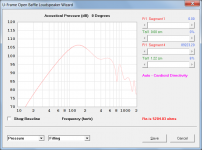
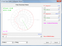
Hornresp takes into account the solid angle into which the H-Frame or U-Frame system radiates. The simulation model is valid at those frequencies where the dimensions of the system and the distance from the wall or walls are small compared to the wavelength, and where the system radiates symmetrically into the solid angle.
To illustrate, Attachment 1 shows the on-axis pressure response of a resistive U-Frame system optimised for cardioid directivity, radiating into quarter space (pi steradians solid angle). Attachment 2 shows the polar directivity pattern for the same system under the same radiation conditions, at a frequency of 100 hertz.
Attachments
- Home
- Loudspeakers
- Subwoofers
- Help to design H frame subwoofer