I thought I'd start a thread on this subwoofer alignment that you rarely see mentioned. For those who don't know, a "passively-assisted" sealed alignment is basically a basic sealed alignment with capacitance added in series with the driver's coils. Do this right and result is an extended bass response.
Wait, that does not sound right does it - capacitors are supposed to reduce the response at low frequencies....
The key here is the AMOUNT of capacitance that's added. Add the right amount and, instead of reducing bass output at low frequencies, you end up extending it, a bit like a vented alignment, without the vent and larger box. While it's supposed to work best with high Qms drivers, it should be possible to use the idea with any sealed alignment, and the impact of added capacitance on a sealed alignment can be sim'd pretty easily with any decent x-over design software.
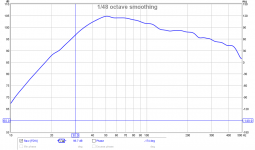
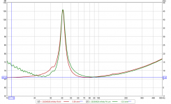
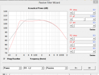
For the example I'm providing here, this involves the use of a fairly cheap car audio 12" driver (I purchased it for $100) with a high Le, installed in a sealed box of about 1 cu.ft.. The end result is a sealed alignment with an Fb of 40 Hz and a classic humped FR response that's characteristic of high Le drivers. (first image).
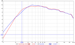
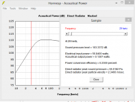
The second image is this same alignment with 1000 uF of capacitance added in series with the drivers coils (two 100V 500 uF NPE capacitors wired in parallel together and in series with the driver's combined 4 ohm impedance coils). The hump in the FR above Fb is flattened and the output below Fb is increased by up to almost 3dB, the equivalent of doubling amplifier output into the subwoofer. Not bad for $15 in parts, eh?") Note that I could have opted for an even flatter passband response by reducing the capacitance to around 800 uF, but that meant give up a bit of response at 20 Hz in the process.
Note that I could have opted for an even flatter passband response by reducing the capacitance to around 800 uF, but that meant give up a bit of response at 20 Hz in the process.
So, what's the tradeoffs?
Well, small box with low F3 isn't going to be that efficient. In any case, I'm using a car audio driver, which are usually designed to be able to take a bit more power and abuse (using 100V caps means that I drive the sub with up to 2.5kW before they blow up, and I won't be driving them anywhere near that power level.
The second disadvantage is that all the output is still from the driver, so more low bass = more excursion = more THD. Interestingly enough, for my particular test, the driver's overall distortion response seems to have improved too, though I'm not sure why. Another mystery to investigate....
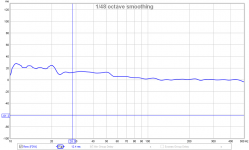
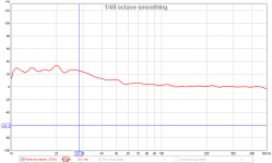
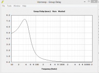
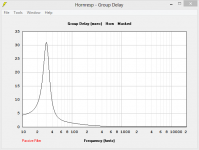
The third one is supposedly poorer GD. Yes, it will worse than a sealed alignment. However, at least for my case, the increase in GD isn't really objectionable - GD has moved from 12.2 to 12.6 ms at 40 Hz, a negligable change. At 30 Hz, GD moves from and 13.3 mS to 30 ms. At 20 Hz, it's at 33.3 ms. In practice it seems to sound pretty good. The last two images show the change in GD when the capacitance is added.
Right now I'm using the driver in a test box, but the intent is to build two of them into two 1 cu.ft. cubes, on for each side of the couch, and use inline capacitance to get the F3 down to 32 Hz. I haven't started the build yet because I haven't decided if I want the drivers down-firing or side-firing.
Note - I suspect the same approach can be used to extend the response of an open baffle woofer or subwoofer. Just take into consideration that the increased response at low frequencies is all from the driver, so make sure that it has enough linear excursion to produce the extra output.
Wait, that does not sound right does it - capacitors are supposed to reduce the response at low frequencies....
The key here is the AMOUNT of capacitance that's added. Add the right amount and, instead of reducing bass output at low frequencies, you end up extending it, a bit like a vented alignment, without the vent and larger box. While it's supposed to work best with high Qms drivers, it should be possible to use the idea with any sealed alignment, and the impact of added capacitance on a sealed alignment can be sim'd pretty easily with any decent x-over design software.
For the example I'm providing here, this involves the use of a fairly cheap car audio 12" driver (I purchased it for $100) with a high Le, installed in a sealed box of about 1 cu.ft.. The end result is a sealed alignment with an Fb of 40 Hz and a classic humped FR response that's characteristic of high Le drivers. (first image).
The second image is this same alignment with 1000 uF of capacitance added in series with the drivers coils (two 100V 500 uF NPE capacitors wired in parallel together and in series with the driver's combined 4 ohm impedance coils). The hump in the FR above Fb is flattened and the output below Fb is increased by up to almost 3dB, the equivalent of doubling amplifier output into the subwoofer. Not bad for $15 in parts, eh?
Note that I could have opted for an even flatter passband response by reducing the capacitance to around 800 uF, but that meant give up a bit of response at 20 Hz in the process. So, what's the tradeoffs?
Well, small box with low F3 isn't going to be that efficient. In any case, I'm using a car audio driver, which are usually designed to be able to take a bit more power and abuse (using 100V caps means that I drive the sub with up to 2.5kW before they blow up, and I won't be driving them anywhere near that power level.
The second disadvantage is that all the output is still from the driver, so more low bass = more excursion = more THD. Interestingly enough, for my particular test, the driver's overall distortion response seems to have improved too, though I'm not sure why. Another mystery to investigate....
The third one is supposedly poorer GD. Yes, it will worse than a sealed alignment. However, at least for my case, the increase in GD isn't really objectionable - GD has moved from 12.2 to 12.6 ms at 40 Hz, a negligable change. At 30 Hz, GD moves from and 13.3 mS to 30 ms. At 20 Hz, it's at 33.3 ms. In practice it seems to sound pretty good. The last two images show the change in GD when the capacitance is added.
Right now I'm using the driver in a test box, but the intent is to build two of them into two 1 cu.ft. cubes, on for each side of the couch, and use inline capacitance to get the F3 down to 32 Hz. I haven't started the build yet because I haven't decided if I want the drivers down-firing or side-firing.
Note - I suspect the same approach can be used to extend the response of an open baffle woofer or subwoofer. Just take into consideration that the increased response at low frequencies is all from the driver, so make sure that it has enough linear excursion to produce the extra output.
Attachments
Last edited:
I'm curious. Doesn't it affect somewhat "damping factor" (i know...it's just a conveniant wait to explain what i try to see) of driver, thus, thd through motion control (i know again, it become esoteric ^^) ? Can you provide distortion figures at the same level since you got rew sweep ?
Brian,
I'd check the impedance curves to see where the ~3dB extra output at 28Hz has come from. My bet is the impedance is 3dB lower with the cap installed.
Chris
That's what I forgot to measure yesterday. Yes, the impedance does change around the system's resonance point. See attached image. At 30 Hz for this particular design the impedance drops from 11.2 ohms to 8.4 ohms. At 32 Hz it goes from 12.1 ohms to 9.72 ohms.
Attachments
I'm curious. Doesn't it affect somewhat "damping factor" (i know...it's just a conveniant wait to explain what i try to see) of driver, thus, thd through motion control (i know again, it become esoteric ^^) ? Can you provide distortion figures at the same level since you got rew sweep ?
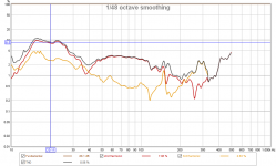
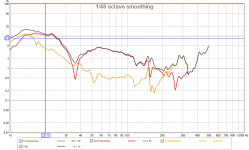
Here are the HD curves. Unfortunately REW does not provide a means for directly comparing HD measurements. The first image is the HD of the unassisted alignment and the second is the assisted alignment at the same voltage drive level.
20 Hz : THD goes from 11.4% to 8.59%
30 Hz : THD goes from 4.28% to 4.16%
40 Hz : THD goes from 2.59% to 1.97%
50 Hz : THD goes from 3.70% to 2.93%
60 Hz : THD goes from 4.31% to 3.60%
Attachments
It is a nice trick to obtain some extension from small closed boxes. In German, this is called geschlossen mit Hochpass (GHP).
Harmonic distortion should not change, assuming the system is equalized to the same frequency response. The capacitor just acts as a passive equalizer. It cancels some of the reactance of the woofers impedance below the resonance peak, hence more current through the voice coil and more SPL. Similarly, it adds reactance above the resonance peak to take some SPL away. The woofer does not know if this equalization is achieved by the capacitor or by other means (for example, a DSP).
Woofer efficiency does not change, because a capacitor is a purely reactive component and the woofer cannot see its prescence. The capacitor can however make the woofer (including capacitor) appear more resistive to the amplifier just below the resonance frequency, resulting in less power being wasted in the amplifier. Class B amplifiers are inefficient when driving reactive loads.
Last edited:
group delay increasing-acceptable for HT ?
Nice!
With lab12c, got low frequency boost ~4dB @29Hz
Nice!
With lab12c, got low frequency boost ~4dB @29Hz
Attachments
Harmonic distortion should not change, assuming the system is equalized to the same frequency response. The capacitor just acts as a passive equalizer. It cancels some of the reactance of the woofers impedance below the resonance peak, hence more current through the voice coil and more SPL. Similarly, it adds reactance above the resonance peak to take some SPL away. The woofer does not know if this equalization is achieved by the capacitor or by other means (for example, a DSP).
I doubt that, because the relation between current through and voltage across a loudspeaker's terminals is not entirely linear. Generally loudspeakers distort less when driven from a very high impedance (current drive) than when driven from a very low impedance (voltage drive), because with current drive, you get rid of a couple of non-linear effects: signal-related changes in the voice coil temperature that change the voice coil resistance have no effect anymore on the current through the voice coil, and the same holds for variations of the voice coil self inductance with the position in the loudspeaker.
With the capacitor, you make something in between pure voltage and pure current drive, so it could very well do something on the distortion.
For a sealed alignment excursion determines the SPL and disortion is dependent on excursion. Eq changes SPL level at a particular frequency not the excursion dependent distortion. From where is the distortion coming down at 28Hz? Its not clear (to me), hope somebody can explain.
Last edited:
We totally agree ^^For a sealed alignment excursion determines the SPL and disortion is dependent on excursion. Eq changes SPL level at a particular frequency not the excursion dependent distortion. From where is the distortion coming down at 28Hz? Its not clear (to me), hope somebody can explain.
All is in Brian REW distortion and spl figures. That why i suppose at least for myself implicitly that 28hz boost comes in this specific case without increased distortion due to the more "current drive" nature given by capacitor boost.
Last edited:
100VDC cap can handle 63V p-p AC voltage, give or take. Some of this depends on the actual ripple current rating of the capacitor and will vary across series, even from the same manufacturer.
There is also a frequency-related metric, lower the frequency the higher the current through the cap, thus cap of suitable ripple current should be chosen.
https://industrial.panasonic.com/cdbs/www-data/pdf/RDI0000/DMI0000COL75.pdf
I would not use a cap above 50% of rated current unless it was for a prototype or experimentation, to ensure long-term reliability.
- Status
- This old topic is closed. If you want to reopen this topic, contact a moderator using the "Report Post" button.
- Home
- Loudspeakers
- Subwoofers
- Passively-assisted sealed alignments