I've tried this driver in small sealed and ported enclosure and not gotten great results.
Would like to try a quarter wave design but with 90 degree angles as I am rubbish with woodwork. Think Homer's spice rack.
Qts is .45 and vas is 1.25 cubic feet. Would this work in this type of enclosure? Don't want it to be too big but could do tall and narrow. Depth im not too worried about either.
One other thing. I have two of these so would a dual sub be better?
Its primarily for music. I don't do any more than 2.5 channels. It will partner with full range drivers and 10 inch woofers as mains. I have about 400wpc stereo sub amp to.power it/them.
Any guidance would be much appreciated!
Cheers
Peter
Last edited:
Looks like a decent candidate for an offset-driver TL.
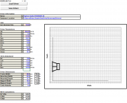
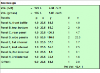
Have a look at the BOXPLAN-TL2 workbook located at my website below. I was able to come up with a 4.25 cu.ft. (net) box, 50% stuffed, that has what seems to be a decent response.
The Subwoofer DIY Page - Horn Folding
Have a look at the BOXPLAN-TL2 workbook located at my website below. I was able to come up with a 4.25 cu.ft. (net) box, 50% stuffed, that has what seems to be a decent response.
The Subwoofer DIY Page - Horn Folding
Attachments
Would like to try a quarter wave design but with 90 degree angles as I am rubbish with woodwork.
Would this work in this type of enclosure? Don't want it to be too big but could do tall and narrow. Depth im not too worried about either.
One other thing. I have two of these so would a dual sub be better?
Its primarily for music. I don't do any more than 2.5 channels. It will partner with full range drivers and 10 inch woofers as mains. I have about 400wpc stereo sub amp to.power it/them.
Driver specs: http://www.daytonaudio.com/images/resources/295-463-dayton-audio-rss265-ho-44-specifications.pdf
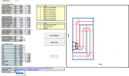
Well, as a general rule, 4*Vas is a nice trade-off between size, power handling or ~139 L and looks good in a lightly stuffed offset driver ~20 Hz TL limited to ~100 W down low depending on the room's gain or 2x larger with 200 W for dual driver loading.
Generally speaking, multiple subs allow more in-room tuning flexibility, so really depends on the room and how flexible where they can be located related to the mains and listening position [Lp].
B0$3 has proven that a 2:1 CR pipe yields optimal driver loading in only ~62.6 L, but the trade-off is a much more rolled off bass with higher Qt drivers, though can handle 200 W and often can blend in better overall in smaller/high gain rooms, so maybe a pair of these would be best overall.
Attached sims assume an 80 Hz/4th order XO in 1.0 pi space.
GM
Attachments
Yeah, only had time to 'run the numbers', but thought it just a close fit and planned to check it later along with adding an end loaded version and it indeed needs a spacer to mount normally. Once again, metric caught me out. 
Anyway, historically I've done these end loaded with a floor mounted driver box and a long vent tube that was 'close enough' to whatever CR I wanted or a 6" dia. [ i.d.] Vs 15 cm dia. ideal size in attached sim.
Indeed! Stiff suspensions [low Vas] make for unacceptably small cabs for low vent tunings, especially if a high power handling one, so would normally recommend morphing a long/large vent BR into an inverse tapered [TQWT] or tapped variant, but after looking up 'Homer's spice rack', understood the need for a 'KISS' design.
GM
Attachments
Apologies for delay replying; long weekend in New Zealand where it rained persistently right where I was.
Thanks Brian and GM for your replies and for the sims. I will need a bit of time to consider these.
The idea of two subs appeals but each time I've tried this the two together never seemed quite as ballsy as one bigger one. Perhaps it is different for quarter wave designs?
Certainly the concept of having two smaller subs appeals in that you can hide two small animals easier than the elephant in the room! My partner isn't a big fan of coffins, but doesn't mind smaller structures.
And I guess it is more successful taming a room with two subs rather than one.
The only problem I see is that to get a big sound you often need big structures. But then the Karlsonator posts would suggest otherwise. And perhaps small quarter wave enclosures act similarly.
So probably that's the direction in which I would rather head.
I've never used Horn Response software before. So reading the txt files is a bit meaningless to me.
But I did understand Brian's first response regarding the cuts I would need to make.
However, I'd really prefer to do one small one first, as that way if it ends up like Homer's spice rack it won't have cost me so much in materials. It will kind of be my first proper build - I have done heaps of speaker builds using cylinders (see below for example) so can rout end caps and mess with waveguides) but none using boxes. However, I have a friend who has a furniture factory so he can cut out the bits using his CNC machine.
Wouldn't mind a link or so to quarter waves though. There are some concepts like 'small offset' for driver mounting (I presume this is to minimise standing waves??) and other bits and pieces I don't profess to understand.
GM what did you mean by this: "Anyway, historically I've done these end loaded with a floor mounted driver box and a long vent tube that was 'close enough' to whatever CR I wanted or a 6" dia. [ i.d.] Vs 15 cm dia. ideal size in attached sim."
And you mentioned something about a 2:1 CR pipe in 63L box.
Again, thanks for your input.
Peter
Attachments
Wouldn't mind a link or so to quarter waves though. There are some concepts like 'small offset' for driver mounting (I presume this is to minimise standing waves??) and other bits and pieces I don't profess to understand.
This might help: The Subwoofer DIY Page - Transmission Line Systems
I'm getting the feeling that pro drivers are better suited to the quarter wave type of subwoofer enclosures than home audio subs.
Is this actually the case?
Also, wouldn't mind hearing from others who have made this type of subwoofer for use in home audio, regarding the quality and quantity of the bass compared with sealed or ported subs.
Not really fussed regarding use in an HT set-up.
Cheers
Peter
Is this actually the case?
Also, wouldn't mind hearing from others who have made this type of subwoofer for use in home audio, regarding the quality and quantity of the bass compared with sealed or ported subs.
Not really fussed regarding use in an HT set-up.
Cheers
Peter
I have decided to go in a slightly different direction for my RSS265HO-44 Dayton subwoofer; still a transmission line but even simpler for construction purposes. No wood, only plastic.
I'm familiar with using PVC enclosures so have decided to stick with PVC piping for the enclosure. Go with what you know, right?
I intend to produce a mini clone of the Nelson Pass El-Pipo design.
I understand there are drawbacks to having the driver at the end of the line but it is really difficult inserting a driver into the side of a cylinder. I can do it with small full range drivers but I think it is impractical with subwoofers. Will use stuffing to try to minimise unwanted resonances.
So the question is: how long must the pipe be?
I'm not sure exactly how to go about modelling this to determine line length. I understand the MJK calc sheet is no longer available for free.
Is it simply a case of downloading hornresp and playing with that using the T/S figures I already have? Is hornresp available for Mac?
Also, I don't yet know whether to do a straight pipe or try to taper it using smaller sections of pipe as the line proceeds vertically. That might be phase two if phase one (straight pipe) works out and isn't ridiculously tall.
I don't mind inserting a bend in the pipe if it works out quite long or can lie it on its side which might make it easier to "blend it in" to the room.
I recall from the NP paper that a 6.5-inch driver results in a 6 foot pipe using 8 inch sonotube so Im guessing around 8 feet is doable using 12-inch diameter pipe?
Initially it would be easier for sure just to use a single section of PVC storm water pipe (or as the significant other calls it 'dunny pipe').
If one works as I hope it might I can use the other to reproduce and have a stereo pair. My ceiling height is 8 foot and 6 inches.
Once I find the line length is it then a matter of determining how long the section of pipe must be according to its diameter?
Cheers
Peter
Attached sims assume an 80 Hz/4th order XO in 1.0 pi space.
Just noticed my sims are mislabeled [driver specs are right], so should be 265HO-44....
GM
Thanks Brian and GM for your replies and for the sims. I will need a bit of time to consider these.
The idea of two subs appeals but each time I've tried this the two together never seemed quite as ballsy as one bigger one. Perhaps it is different for quarter wave designs?
The only problem I see is that to get a big sound you often need big structures. But then the Karlsonator posts would suggest otherwise. And perhaps small quarter wave enclosures act similarly.
So probably that's the direction in which I would rather head.
I've never used Horn Response software before. So reading the txt files is a bit meaningless to me.
I have done heaps of speaker builds using cylinders (see below for example)
Wouldn't mind a link or so to quarter waves though.
GM what did you mean by this: "Anyway, historically I've done these end loaded with a floor mounted driver box and a long vent tube that was 'close enough' to whatever CR I wanted or a 6" dia. [ i.d.] Vs 15 cm dia. ideal size in attached sim."
And you mentioned something about a 2:1 CR pipe in 63L box.
Again, thanks for your input.
Peter
You're welcome!
True, depending on the room's acoustics and where each sub is located Vs a single dual sub in a high gain location, so like most things the choice is what best overall meets the performance, etc., needs of the app. Same for any type speaker alignment, just the 1/4 WL alignments typically have more gain BW and/or more gain for a given BW, though normally at the expense of a larger cab.
Indeed, especially for TLs: https://www.diyaudio.com/forums/subwoofers/354352-subwoofer-help.html#post6206974
The Karlsonator OTOH is a 6th order bandpass alignment [BP6], aka tapped TL [TTQWT], tapped horn [TH], etc.. These typically have the most [mid] bass Vs box size due to the pipe folding back on itself such that both sides of the driver's output is combined at the terminus [mouth] of the pipe/horn, i.e. the path-length between them is 1/2 WL/180 deg away.
HR's .txt files don't mean much to anybody if they don't load the program, then load the file in it to view all the particulars, different calculated plots, so no time like the present.
Understood, I've done many more pipe speakers than boxes since I was mostly interested in building column/tower [TL, MLTL] alignments and had free access to all kinds of round, rectangular pipes in a wide range of sizes/materials.
This is the definitive 1/4 WL site: Quarter Wavelength Loudspeaker Design
I was referring to my using various pipes to make cylindrical end loaded 'Sonotube' or 'El Pipo' type woofers, though for the box part I normally used rectangular ceramic or concrete pipe and heavy duty cardboard tubes or the occasional scrap plastic or metal pipe for the vent.
'CR' = Compression ratio, i.e. the ratio of driver effective piston area [Sd] to pipe area.
Yes, one of the sims is an offset driver TL in ~63 L, then added an end loaded version that's only ~60 L, but as Brian noted, in each case this will require either mounting the driver motor out or adding a spacer, so all things considered [driver sag*, build complexity, a bit more mid bass at the expense of maybe more damping required], building the end loaded one with either a bigger pipe or bigger pipe reduced to the simmed smaller one.
* % sag: Resources - Woofer Mount Up Down
GM
I'm getting the feeling that pro drivers are better suited to the quarter wave type of subwoofer enclosures than home audio subs.
Is this actually the case?
Actually, mobile audio and specialty HT woofers are. Pro drivers are more mid bass - up oriented, so are great for music that doesn't go below ~40 Hz.
GM
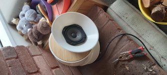
Oh my goodness. I haven’t had bass quality or quantity in my system before making El-Pipo junior. And there’s only one of them!
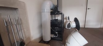
What I did was find what PVC pipe I had lying around and joiners. that happened to be 2x1m pieces so in total the line is 2100mm long, and the internal diameter of the pipe is 236mm. Handy that because the surround diameter is about 235mm or so. The Dayton driver fits just so with the magnet poking out and acting as a base for the upright pipe. There’s a 90 degree join at roughly the height of the equipment rack so I can hide the horizontal section of pipe in behind the TV.
I’m not exactly sure how long the line should be. But already the system is sounding pretty incredible. Definitely this is better bass than my ported 15-inch Dayton, thought enclosure size of that wasn’t ideal. I would like to optimise line length for the T-Line though.
Thanks for the help with this Brian and GM.


Oh my goodness. I haven’t had bass quality or quantity in my system before making El-Pipo junior. And there’s only one of them!
What I did was find what PVC pipe I had lying around and joiners. that happened to be 2x1m pieces so in total the line is 2100mm long, and the internal diameter of the pipe is 236mm. Handy that because the surround diameter is about 235mm or so. The Dayton driver fits just so with the magnet poking out and acting as a base for the upright pipe. There’s a 90 degree join at roughly the height of the equipment rack so I can hide the horizontal section of pipe in behind the TV.
I’m not exactly sure how long the line should be. But already the system is sounding pretty incredible. Definitely this is better bass than my ported 15-inch Dayton, thought enclosure size of that wasn’t ideal. I would like to optimise line length for the T-Line though.
Thanks for the help with this Brian and GM.
You’re barely hitting an Fb of 40hz with a mid 20s Fs and a Qts that might allow mid 20s or so. There’s smoke, but you haven’t seen the fire�������� Maybe Stick 160mm of 275cm2 ‘solid’ in the last 3/4 and see if you like it? It takes tuning down to about Fs without the peaky nature of the oversized pvc pipe at 40hz you have now. It pushes things at RMS power, air velocities of 22m/sec at the open end and Xmax near that level of input power and it’s intensely loud output level..
Cool project! I like plastic pipe stunts too. However, mines only a 4” driver at Fb 70hz in 45cm2.
Attachments
Last edited:
I did a quick calc and I think I need more pipe, another 40cm or so to get down to 28hz and another 120 to get to 21hz.
Thx BW for the tip. I had stuffed the line from beginning to end so will try last 3/4 only. My partner said to remove the first attempt but when she eventually noticed this one she just sighed a little so will take that as mild positive reinforcement. Glad I cleaned the pipes better!
Thx BW for the tip. I had stuffed the line from beginning to end so will try last 3/4 only. My partner said to remove the first attempt but when she eventually noticed this one she just sighed a little so will take that as mild positive reinforcement. Glad I cleaned the pipes better!
- Status
- This old topic is closed. If you want to reopen this topic, contact a moderator using the "Report Post" button.
- Home
- Loudspeakers
- Subwoofers
- Quarter wave enclosure for Dayton RSS265HO-44?