Flip one driver so the cone is firing into the box and also flip it's connections to compensate .. then you can get some push-pull even harmonic cancellation going on . Should sound even cleaner that way
See front / back arrangement .. ignore the text that says isobaric
See front / back arrangement .. ignore the text that says isobaric
Attachments
Last edited:
Thanks for that advice, Zobsky, I will give that a crack, and given the rear driver isn't visible it wont matter that it is magnet out!
I have each of the driver's 4ohm voice coils wired up in series for 8 ohms and then paralleled for 4 ohms. But it shouldn't matter if I simply switch + for - on the one driver I flip, right?
How is it that harmonics are different/advantageous in this configuration? (a link if you have one plse).
I have each of the driver's 4ohm voice coils wired up in series for 8 ohms and then paralleled for 4 ohms. But it shouldn't matter if I simply switch + for - on the one driver I flip, right?
How is it that harmonics are different/advantageous in this configuration? (a link if you have one plse).
So it's all over with the TLine subwoofer using the opposed 10-inch Dayton RSS265HO-44s. The SWMBO said the drainage system in the living room had to go. So dismantled it in the weekend.
So instead, the box is small enough I can hide it behind the TV and just use it as a sealed sub. Which is what I've done because I had never tried this set-up sealed before.
It's not bad. However, it probably isn't optimal because the internal volume isn't quite right.
The specs suggest 0.55cubic feet sealed for one sub, so Im guessing that means 1.1cubic feet for a pair of them, correct?
And I guess that is for the internal volume without the drivers?
So how does one calculate the correct cube size if using, say, 18mm ply?
Bummer. 
Correct.
Right, [Vb] = net volume, but sealed is very forgiving, so doesn't need to be real accurate.
Since we're talking about internal volume, the material thickness is irrelevant, so let's assume 1.5 ft^3 = 1.5*1728 = 2592"^3 = [2592]^0.33 = ~13.75" i.d. [inside dims] cubed, just big enough to mount two back to back [bipole] wired in phase or if there's room and no kids/pets issues, then as zobsky noted earlier, mount one motor out and reverse wire it out of phase [push-pull] for ~ cancelling out 2nd order distortion.
Since we want 18 mm [0.75"] thick overlapping panels:
[2] 13.75" x 13.75" top/bottom [inset]
[2] [13.75" + 1.5"] = 15.25" x 15.25" left, right sides
[2] 13.75" x [13.75" + 1.5"] = 15.25" front, back baffles [inset]
Between being such a small bipole cab constructed with 18 mm void free plywood, best to just mass load it with something that totals at least as heavy as the assembled sub perched on top and skip internal bracing, just make sure to bond it together with an industrial exterior wood construction adhesive.
GM
Last edited:

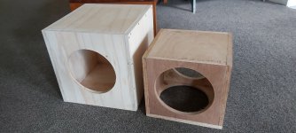
So I made up another box for the Daytons as above - thanks for the measurement help GM -and learnt quite a bit about box building along the way.
It digs lower than the old one which was not optimised for sealed operation - it was part of the TL sub with 3.5m of plastic tubing attached - but I miss the visceral drama of the transmission line.
So the next move is to build a TL according to Patrick Bateman's easy-to-do TL guide. Have inputted and optimised the RSS390 for a tapered TL I just need now to sort out how best to implement this. In other words, a simple build.
It will be interesting to compare the result with an optimised sealed sub (admittedly using two 10-inch drivers vs 1x15). The TL will likely be bigger but am hoping also better.
Attachments
- Status
- This old topic is closed. If you want to reopen this topic, contact a moderator using the "Report Post" button.
- Home
- Loudspeakers
- Subwoofers
- Quarter wave enclosure for Dayton RSS265HO-44?