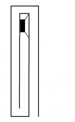
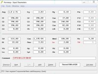
I have been thinking about and simulating variations of this tapped pipe for a while now. Today the stars aligned with the moon, my morning tea and my morning mood and access to the car, so I loaded Cypress Hill into my car stereo and went and bought some 22 mm particle board for a cheap and easy to build prototype based on my B&C 12PS100.
I hope this tapped pipe will have it all. Reasonably high efficiency, a great midbass punch and attack, reasonably small footprint, cheap and easy to build and a great extension downwards into the abyss. These desirable properties seldom walk hand in hand, but I hope a healthy dose of positive acoustic feedback will create a lot of synergistic effects enabling the presence of all those desirable properties at once.
The name TP12LL34 comes from "tapped pipe Long L34". "Duality" comes from the fact that the great extension downwards does not stand in opposition to a great midbass. Positive feedback is the pressure that the last long section (L34 in Hornresp lingo) exerts on the cone throughout the midbass.
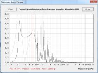
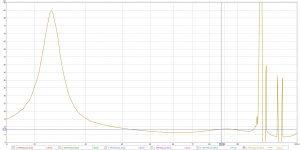
Here is the Hornresp simulation of cone pressure on both sides of the cone overlapped. The Grey line is the throat pressure and the black line is the mouth side of the cone.
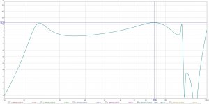
There is a lot of positive acoustic feedback from 50 Hz somewhere up to almost 100 Hz. This can also be seen in the spl graph where a "normal" tapped horn with substantially shorter L34 never have such a large and low Q mid bass peak and wide usable bandwidth.
shouldn't the sections be summed as PAR instead of CON?
It does not matter with straight non expanding sections.
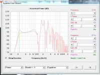
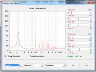
With and without EQ. It is quite easy to EQ this design to a "smooth" response if desired.
I am not overly worried about the peaks. They seem to give a nice character for HT and hifi if not overdone. The low frequency peak will add a very tactile and physical "breathing" of the body of instruments. You can sense a large scale "breathing" in the whole house with this kind of tapped pipe. Perfect for home theater. Very convincing and entertaining with typical Michael Bay movies. Might need a dB or two of EQ for Hifi to stop overwhelming the rest of the sound reproduction.
The mid bass peak is very low Q with very flat GD throughout the whole "punch and attack" range. It should normally not need any EQ, except if there is a bad room acoustic interaction (room peak coincides with tapped pipe peak).
That is nothing that a small amount of well placed internal carpet and damping wool can´t remedy. +15 dB at and above 150 Hz is a typical simulation artifact. Hornresp treats the walls of the enclosure as infinitely stiff and solid, but 22 mm particleboard is anything but that.
I will post measurements once it is built.
I will post measurements once it is built.
I've tossed designs that have shown less out of band noise than that - they never made it from paper to wood. That level of out-of-band noise can make an otherwise good BP sub sound awful, and I'm sure the same applies to tapped 1/4 wave designs, as they're basically another form of series-tuned 6th order BP.
Yes, a few dB will be shaved off due to losses that are not shown in Hornresp, but 15dB is quite a big mountain to cut down - 3dB of losses will still leave you with a 12dB out of band "mountain range".
That range (150 Hz ~ 350 Hz) might be difficult to deal with by damping the sides of the enclosure, and damping it too much might end up killing the response at the low end of the spectrum.
Have you tried extending the S1-S2 length, and then simulating damping in that section in Hornresp? I've found that could do a pretty good job of cutting down the out of band "noise", and being able to sim the damping effect in Hornresp would allow you to re-tune the enclosure accordingly to make up for and loss of output at low frequencies.
The layout looks fairly simple - if I have some time this weekend I'll put together a BOXPLAN workbook for it - that would make it easier to go back and forth between Hornresp and the design to come up with something as close to ideal as possible.
Why this concern about out of band noise? I agree that it is not desireable, but any half decent active filter will cut it down to nothing if used correctly, put a 48dB/Oct LR at 80hz (I'm just guessing here) and I'm fairly sure you will not be able to hear it, perhaps not even messure it, once the design is integrated with the rest.
If we where dealing with less agressive filters like first or second order I would voice the same concerns, and lower order filters can be easier to deal with when it comes to integration, still, a flat out of band response is good, but it does not help matters unless it is equally flat in the time domain.
If we where dealing with less agressive filters like first or second order I would voice the same concerns, and lower order filters can be easier to deal with when it comes to integration, still, a flat out of band response is good, but it does not help matters unless it is equally flat in the time domain.
Why this concern about out of band noise?
Out of band noise that's 15dB above the passband level will result in increased THD - that out of band curve will amplify any HD (and motor noise produced by the driver) in the system's passband. Should be avoided if possible.
Out of band noise that's 15dB above the passband level will result in increased THD - that out of band curve will amplify any HD (and motor noise produced by the driver) in the system's passband. Should be avoided if possible.

How can upper out of band noise amplify in band (or in intended range) distortion if the frequencies required for said out of band noise is never present (or greatly reduced) in the signal in the fisrt place?
Upper out of band harmonic distortion components generated by in band (or range) frequencies is another matter, but again, what ever levels of distortion present in the upper out of band "noise" (it is a response graph remember, not a HD graph) wil be grately suppressed by appropriate processing.
If I'm still not getting your point forgive me, I'm currently not at my best due to high levels of out of forum harmonic distortion
A electrical input signal 110hz gives a H2 distortion acoustic peak at 220hz. Equing input at 220hz won't have any effect on it, it is too late. If one would want to suppress this H2 spike electrically, he would have to produce at input the same level peak at 220hz but out of phase. Reducing the input at 220hz, has no effect on it.
For this distortion H2, in your design, this is not really a problem as you said, you doesn't have so much input at 110hz. But the same work for H3 distortion at let say around 74hz wich give his H3 at around 222hz. And here, we are in your used bandwith.
Whereas acoustic low pass totally works on both original signal, and it distortion component. Your designs out of band spike clearly increase inband distortion (H3 around 74hz for example). That is mathematical.
Just to complete, when looking at spl curve from datasheet, curves are the resultant spl level at each frequency of a input signal. This mean a signal at a frequency gives let say 100db, but maybe only 98db fundamental + 2db of different frequency sound from distortion+noise.
Last edited:
An alternative to TH; Here are two versions of Compound horns using equal cross section area and cut off frequency. They both provide greater upper extension and sensitivity. The two examples differ by canceling different resonances with different pipe segments.
The discontinuity around 185 Hz should be treatable by adding a stub to cancel out the third harmonics of horn segment 2. However, I don't know how to model it. This would increase bandwidth even further, alternatively ease integration.

The discontinuity around 185 Hz should be treatable by adding a stub to cancel out the third harmonics of horn segment 2. However, I don't know how to model it. This would increase bandwidth even further, alternatively ease integration.

The reason I don´t design speakers like that is seen in the GD graph. Those small kinks in the spl graph might not look like much but is easy to hear in real life.
To sum two resonators outside of the box is seldom a good idea. They compress and become turbulent at different spl and will sum very differently dependent on power input, placement and radiation angle.If you need to adjust to within a cm or two to get a simulated flat response then it does not take much to throw the summation off in real life.
Timing and a good summation is often much more important then a flat spl curve or some small theoretical simulation artifact way above the passband in my experience.
I am waiting for the glue to dry. The 4 pieces that make out the baffle and the bracing connected to the baffle has all been glued, clamped and screwed together to create a strong and stiff platform for the driver to work from.
Cypress Hill and my two guinea-pigs keep me company this rainy day while I work towards some real world measurements and listening impressions.
Upper out of band harmonic distortion components generated by in band (or range) frequencies is another matter
That's exactly the HD that we're talking about here. As that HD is going to be generated by the speaker, it's not going to be reduced by any processing done before the signal reaches the speaker.
It's not that esoteric, those are subsTo sum two resonators outside of the box is seldom a good idea.
In acoustic live, instrument sums in air...And in everydays life, everything sums in air. Stereo is about summing left and right ways...I won't go depper about that, there's a lot of master here about that.
Whatever your sub manage to do, don't forget the image of the ripple done by a stone left in water. In low frequencies, it's more like the effect of moon on earth, full level of water get higher, and lower. We're in pressure range. Even with the most controlled sub (mfb with accelerometer or B&C Ipal pressure sensor motion controlled), air will resonate, and won't stop moving even if speaker stop. Imagine moon not moving as regulary...It would be really problematic

If it was so, a lot of wind instrument wouldn't work...To sum two resonators outside of the box is seldom a good idea. They compress and become turbulent at different spl and will sum very differently dependent on power input, placement and radiation angle.If you need to adjust to within a cm or two to get a simulated flat response then it does not take much to throw the summation off in real life.


It's seems you've convinced yourself about a lot of stuff. Acoustic is not something new. It has been studied since a few time, there's a lot of interesting literrature
I can share the world how much suggar taste good to me. Still i won't try to proove this is most balanced food.
Last edited:
About +/- that, just to share, on a french forum, it has been tested passive electrical damping of H3 fundamental frequency of cone resonnance. With motor electrically damped (low qes), back emf generated can be damped, dissipated, and so cone resonnance spike at his h3 fundamental is limited. Post of the "18 Jan 2017 21:40" from here :That's exactly the HD that we're talking about here. As that HD is going to be generated by the speaker, it's not going to be reduced by any processing done before the signal reaches the speaker.
<<Reduction de la distorsion par reseau passif>> - 30091477 - sur le forum <<Discussions Generales>> - 1472 - du site Homecinema-fr.com
We see pretty well the distortion reduction at 682hz.
There's probably some subtilities about this kind of damping with class D amp, as it seems to be explained fact in IPAL pressure sensor whitepaper... But i'm not really versed in electronic part. The same way, I won't argue about current drive and mbf...i suspect i need 10-20 years more reading the forum to get ready
About +/- that, just to share, on a french forum, it has been tested passive electrical damping of H3 fundamental frequency of cone resonnance.
Unfortunately my french is awful - I have no idea what they're trying to say on that site. It looks like they're using some sort of passive filtering before the speaker, and any passive filtering done on the passband will impact the HD profile as well. And from my, albeit limited experiments, the % of HD caused by cone resonance varies with input level as well.
It's a simple passive network impedance trick damping back emf. It play with impedance on precise bandwith. It really need few component, so i feel in some case it can be interesting to implement. The linked thread is only one example with great measured REW result curves. We've got interesting people on this forum, but for the moment, i'm not ready to understand even if i'm FrenchUnfortunately my french is awful - I have no idea what they're trying to say on that site. It looks like they're using some sort of passive filtering before the speaker, and any passive filtering done on the passband will impact the HD profile as well. And from my, albeit limited experiments, the % of HD caused by cone resonance varies with input level as well.
EDIT : Sorry, it's start to become off-topic !
Last edited:
- Home
- Loudspeakers
- Subwoofers
- TP12LL34 Duality and positive feedback