It's a simple passive network impedance trick damping back emf.
Doesn't the amplifier already do that?
")
Doesn't the amplifier already do that?
 I woud have better said "undamp" since it raise impedance
Last edited:
I think we better wait and see how much of a real world noticable issue (or not, my guess) the upper out of band distortion really is in this case, for now I'm more intrested in taking part of the build progress and nedless to say the result, this is Johannes design and build, and I belive it to hold alot of promise.
Tapped pipe (or contant area tapped horn) is a well known principle, and one that is very efficient in relation to the required external volume, if he can add a bit of passband extension and remedy the mid passband dip to some extemt, and spice it up with some midbass punch, all without adding significantly to the build complexity, well then thats progress in my book.
Tapped pipe (or contant area tapped horn) is a well known principle, and one that is very efficient in relation to the required external volume, if he can add a bit of passband extension and remedy the mid passband dip to some extemt, and spice it up with some midbass punch, all without adding significantly to the build complexity, well then thats progress in my book.
What does the displacement-limited theoretical SPL for that design look like? The driver's specs suggest a pro audio 12", and those usually have limited Xmax as compared to say a 12" driver designed for HT subwoofer use.
For comparison purposes, the attached is the theoretical displacement-limited output of a Dayton Audio RSS15HFA 12" driver (14.3mm Xmax) in a damped 175 liter offset TL design.
For comparison purposes, the attached is the theoretical displacement-limited output of a Dayton Audio RSS15HFA 12" driver (14.3mm Xmax) in a damped 175 liter offset TL design.
Attachments
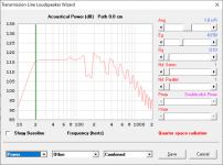

This is the theoretical max spl based on 8 mm xmax and 700 watts of power.
Based on my experience with lots of tapped pipes with lots of positive feedback I would say 120 dB max spl from 23 Hz to 110 Hz with some extra headroom (10 dB) in the mid bass. All in 1,0 Pi radiation angle and without the room gain.

Dry mounting of all the parts to see that they all fit before I commit to the build.
B&C Speakers from first post hornresp pic record label. Nice oneWhat does the displacement-limited theoretical SPL for that design look like? The driver's specs suggest a pro audio 12", and those usually have limited Xmax as compared to say a 12" driver designed for HT subwoofer use.
For comparison purposes, the attached is the theoretical displacement-limited output of a Dayton Audio RSS15HFA 12" driver (14.3mm Xmax) in a damped 175 liter offset TL design.
 .
.Well... people have been canceling resonances ever since the Voight-horn (or earlier?) was invented. Can you please show an example you've built/designed or listened to where this would been its major drawback?
If a discontinuity in GD in an infinitesimal small interval would be detrimental, it would have shown here for example:
Compound loading 6th order quarterwave "Super Planar" horns and pipes concepts/builds
I reed you like the response of the cab you're building. I've built a couple my self of similar design (though some years ago now...) and I agree with your description. However, I've come to the conclusion that they tend to add its own character to the sound of which I finally got tired of. I don't worry about distortion, they all sounded very clean and impressive (at first). What I did not like after a while were the suck-out at the upper end and the high GD at the lower end.
You're right about that my proposals are more sensitive to folding and driver mounting position. But as performance goes up, tolerances goes down...
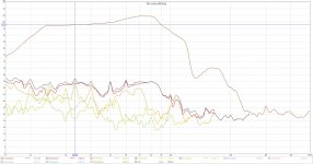
GD of your design in gray and the 167-liter version.

I don't see any problems with summation, 1/4 wavenength at 172 Hz is still 0,5 meters...
That was that...
Now I'm looking forward to your build and impressions Keep up the good work and let us know what's happening!
If a discontinuity in GD in an infinitesimal small interval would be detrimental, it would have shown here for example:
Compound loading 6th order quarterwave "Super Planar" horns and pipes concepts/builds
I reed you like the response of the cab you're building. I've built a couple my self of similar design (though some years ago now...) and I agree with your description. However, I've come to the conclusion that they tend to add its own character to the sound of which I finally got tired of. I don't worry about distortion, they all sounded very clean and impressive (at first). What I did not like after a while were the suck-out at the upper end and the high GD at the lower end.
You're right about that my proposals are more sensitive to folding and driver mounting position. But as performance goes up, tolerances goes down...
GD of your design in gray and the 167-liter version.
I don't see any problems with summation, 1/4 wavenength at 172 Hz is still 0,5 meters...
That was that...
Now I'm looking forward to your build and impressions Keep up the good work and let us know what's happening!
The reason I don´t design speakers like that is seen in the GD graph. Those small kinks in the spl graph might not look like much but is easy to hear in real life.
To sum two resonators outside of the box is seldom a good idea. They compress and become turbulent at different spl and will sum very differently dependent on power input, placement and radiation angle.If you need to adjust to within a cm or two to get a simulated flat response then it does not take much to throw the summation off in real life.
Timing and a good summation is often much more important then a flat spl curve or some small theoretical simulation artifact way above the passband in my experience.
God morning Johannes, this is your diyaudio wakeup call (in writing) (on a forum) (not the best way perhaps come to think about it)
It's going to wonderful standard grey skies with slight drizzle and just above freezing this morning so get out of bed/coffin/canot (what ever applies) and get to work bringing us some updates on the build, I have been up since 03:30 this morning (true) with rather stale popcorns refreshing this page you know (not so true, but stll).
I have not heard any distant rumbling so far so I thought I'd better check up on the progress.
Thanks for simulations and ideas Petter Persson!!
I appreciate your contributions even though I don´t agree with you on some technical points.
There is a very large difference between say a BR and a high order bandpass when it comes to summation outside of the box.
A summation of two quarter wave resonators needs some mutual resistance to work against so that they affect each other. A BR has a small narrow bandwidth port contribution in the lowest part of the intended passband. There is a large difference between summing two wide bandwidth quarter wave resonators and a single Helmholtz with he direct radiation of the driver.
Regards,
Johannes


In this build there is a distinct kink in the spl and GD graph as both measured and simulated. The chamber behind the driver turned out a little larger then I intended which made the summation worse then my first simulations predicted.
The summation defect is very audible with 90 Hz 24 dB/octave xover. But is it of minor importance when playing 142 dB at 30 Hz in a car.
This isn't what i asked. Playing a sinewave of 30 hz, measuring 142dB, doesn't mean there is 142 dB output at 30 hz. You mesured 142dB of total 30 hz fundamental+harmonics+noise. So you don't know what was the level of the produced fundamental. No problem. But this is of no use for evaluating sound quality of a system.
Do you have it measured integrated with full system measurement ?View attachment 793462
View attachment 793463
View attachment 793464
In this build there is a distinct kink in the spl and GD graph as both measured and simulated. The chamber behind the driver turned out a little larger then I intended which made the summation worse then my first simulations predicted.
The summation defect is very audible with 90 Hz 24 dB/octave xover. But is it of minor importance when playing 142 dB at 30 Hz in a car.
The old TPCH with a very powerful spl competition 12 inch driver was a sound quality oriented build but with a slight balance toward a physical impressive reproduction of bass. Today it is being used as a quite capable home theater sub.
This TP12LL34 I am building in this thread is a pure sound quality oriented build. It is a adventure where I test large amounts of positive feedback to increase the ability to reproduce complex nonlinear non-sinusiodal wave shapes and to shape the tone curve to my liking.
This TP12LL34 I am building in this thread is a pure sound quality oriented build. It is a adventure where I test large amounts of positive feedback to increase the ability to reproduce complex nonlinear non-sinusiodal wave shapes and to shape the tone curve to my liking.
Thanks for your examples and explanations. I did some reverse engineering using your simulated SPL plot. It gave a shift of 10 dB at the kink. If I apply that to my 167-liter-125- Hz resonance nulling, it gives me a 5 cm too long segment and a GD of 80 ms. If I make it 5 cm too short, it also makes the kink 10 dB but GD gets -120 ms instead.
This makes me think whether you heared the GD shift, SPL shift or both. Your thought on this? The SPL was reduced by some 10-15 dB already at the kink by being out of bandpass. Did you listen to the sub only or was there a top system too?
As you could see in the example i linked to, there was no SPL shift in the bandpass below 135 Hz. If so (in a min phase system as this), there should be no phase/GD shift either and thus not be audible. However, to match simulation to build within a cm or two requires some iteration I guess. The reward would be greater sensitivity and bandwidth.
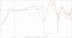
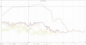
Here are some first measurements of this little beast.
I have overlaid the raw response with the as-used response with EQ and Xover using my MiniDSP 2X4HD. All the measurements are taken indoors with an Umik microphone and REW. Microphone 5 cm from the port on one side of the box (there are two ports. One on each side). No smoothing. The distortion graph has some small peaks where it does indeed get close to a single percent THD, but overall the THD is centered around the 0,5 percent level for most of the passband.
When scanning though the passband in the distortion graph it is very clear that the distortion is highest in the lower part of the passband where there is no acoustic positive feedback. From 50 Hz and upwards the positive feedback makes the driver behave like it had a lot more Bl and moving mass - a much more powerful driver.
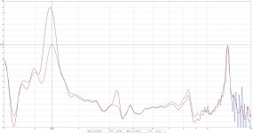
I measured from 10 Hz to 500 Hz in order to get a decent amount of the out of passband ripple and distortion. The ripple peaks 6,3 dB (not quite 15 dB) above the peak of the passband. I guess there are other ways of weighting this kind of comparison but I just took the most obvious example first. I am sure someone will tell me a better way more to your liking if anyone wants it.
I have overlaid the raw response with the as-used response with EQ and Xover using my MiniDSP 2X4HD. All the measurements are taken indoors with an Umik microphone and REW. Microphone 5 cm from the port on one side of the box (there are two ports. One on each side). No smoothing. The distortion graph has some small peaks where it does indeed get close to a single percent THD, but overall the THD is centered around the 0,5 percent level for most of the passband.
When scanning though the passband in the distortion graph it is very clear that the distortion is highest in the lower part of the passband where there is no acoustic positive feedback. From 50 Hz and upwards the positive feedback makes the driver behave like it had a lot more Bl and moving mass - a much more powerful driver.
I measured from 10 Hz to 500 Hz in order to get a decent amount of the out of passband ripple and distortion. The ripple peaks 6,3 dB (not quite 15 dB) above the peak of the passband. I guess there are other ways of weighting this kind of comparison but I just took the most obvious example first. I am sure someone will tell me a better way more to your liking if anyone wants it.
Attachments
- Home
- Loudspeakers
- Subwoofers
- TP12LL34 Duality and positive feedback