How many things are wrong with this proposed/crossover design?
Even using Non-Polarized Electrolytic for cost reasons, this would be an expensive circuit.
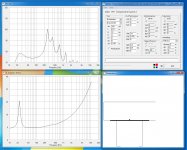
This would be a six 12" woofer setup in a stacked Ripole/Linkwitz fashion, cone to magnet with an overall height of about 30". Total cone area equals ~ two 21" woofers.
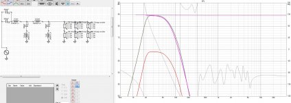
Woofer enclosure was modelled in AJhorn 7.0 for one woofer. Impedance and frequency response were copied to VituixCAD where the crossover circuit was "designed" (<- a term I use very loosely). I was shooting for an LR4 at 75Hz.
These are very cost effective high QTS woofers (QTS=1.3) and efficiency was thrown out the window in favour of frequency response.
Even using Non-Polarized Electrolytic for cost reasons, this would be an expensive circuit.
This would be a six 12" woofer setup in a stacked Ripole/Linkwitz fashion, cone to magnet with an overall height of about 30". Total cone area equals ~ two 21" woofers.
Woofer enclosure was modelled in AJhorn 7.0 for one woofer. Impedance and frequency response were copied to VituixCAD where the crossover circuit was "designed" (<- a term I use very loosely). I was shooting for an LR4 at 75Hz.
These are very cost effective high QTS woofers (QTS=1.3) and efficiency was thrown out the window in favour of frequency response.
Attachments
")
Greetings, @DaveFred.
Are we talking 3 per side or 6 per side or a single woofer section with 6 woofers?
Six per side.
Acoustically an extremely inefficient system. I don't know AJHorn program, but looks like it is showing something like nearfield response of the "frontside" only - forgetting the backside radiation leaking to the "room".
This kind of systems are extremely difficult to simulate even in free-field. The backwave leaks out through a chamber too, the opening of which is somewhere (down in the simulation picture). Because of the long wavelength, soundwaves will eventually start cancelling/summing depending on pathlength and frequency. When we put this thing in a room and perhaps even on the foor and near a wall, everything changes again...
How about making a quick and dirty particle board proto and measuring it?
dB v2
Extremely LARGE Systems / Systems with Multiple Radiation Sources
Subs having multiple radiation sources will be placed so that the driver is closest to the microphone, or equidistant in the case of multiple drivers and any ports, passive radiator's, or other auxiliary radiators. The DUT will be oriented with all of the radiation points as close to the microphone as the cabinet geometry allows. Systems having multiple radiation points, or having drivers firing from 2, or more enclosure faces will have measurements taken at a distance of 1m, 2m, 4m and 10m's and these measurements will be used to develop a compensation file in order to properly compare the output power and response of these systems against conventional, unidirectional, forward radiating systems. With some subs the enclosure itself is large enough and the distance between radiation elements is enough, that the system itself is providing some boundary loading at a distance of only 1m. The distance between radiation points on the system may be large enough to account for a significant percentage of a 1m, or even 2m measurement distance, which will misrepresent the total output makeup of the system by exaggerating the output of the closest radiator and under-representing the output of those radiators that are further away relative to the microphone, or with a different facing. Some extremely large systems can still exhibit some effect at 2 meters. A longer distance 10m measurement reduces these errors by allowing all of the radiation from a system that may have multiple radiation points to blend better and become subject to the inverse square law by the time the output reaches the microphone. For these reasons the standard measurement distance used for most systems is 2 meters and not 1m as it represents too many compromises for larger systems. Some larger more powerful systems are measured at 4m.
Last edited:
- Status
- This old topic is closed. If you want to reopen this topic, contact a moderator using the "Report Post" button.