Maybe Not
Voicing your system using a DSP will expose you to more complexity than that presented by servo control issues that are totally user transparent.
Besides the furniture envelope, net internal enclosure volume is your only other design constraint.
You only need one unit, not two. and you have plenty of space for the custom enclosure that will be required. Note that the unit comes with its own plate amp as well. Duplicating unit performance at a lower cost is not likely.
WHG
The Rythmik makes it too complex / expensive and probably will not fit my shallow enclusure.
Voicing your system using a DSP will expose you to more complexity than that presented by servo control issues that are totally user transparent.
Besides the furniture envelope, net internal enclosure volume is your only other design constraint.
You only need one unit, not two. and you have plenty of space for the custom enclosure that will be required. Note that the unit comes with its own plate amp as well. Duplicating unit performance at a lower cost is not likely.
WHG
OB is worth considering, I have OB subs and love them. They may not work well though so close to the room boundaries, it depends also on your listening position. It would be simple to do a mock up though with any woofers you have to hand or can get hold of to see if it's a viable option.
Adding "H" panels and wings can extend the annihilation distance. I think you can view the phase cancellation is a matter of proportions of distances, bouncing off surfaces, and the like. Also, the driver's resonance will give a boost to the low end.
In other words, hard to say... but easy to try. Sure beats endless soul-searching to mistakenly believe there are magically correct T/S parameters.
Labyrinth sketch looks good. good to have exit door remote from driver (as in your sketch) so that it doesn't interact acoustically with the driver. Like I said, hard to make it not work.
Contrary to common opinion, there's nothing beneficial about a box. True horns aside, a box is there to solve the phase cancellation issue. But there are better sounding solutions.
B.
Last edited:
It's not just the distance but the angle too, you have the dipole radiation at 90 degrees instead of 180 which is going to shift the null more towards the listening position.Here a quick and dirty suggestion for the OB solution.
I can have the sub and exit change position to rotate the cabinet 180 degrees.
In the drawing the sub is to the right (closer to the window) and the exit port towards the plywood shelf with the pre-power amp combo.
The center of the frame is also centerline for the listening position on the couch.
In the drawing the sub is to the right (closer to the window) and the exit port towards the plywood shelf with the pre-power amp combo.
The center of the frame is also centerline for the listening position on the couch.
Any objections or benefits to have the woofer angled forward to the listener ?
And if beneficial would 2 smaller woofers parallel (more flexible in positioning than one large woofer) have more benefits ?
My brain is coming op with all kind of (silly ?) ideas ... just want to reflect on them ...
And if beneficial would 2 smaller woofers parallel (more flexible in positioning than one large woofer) have more benefits ?
My brain is coming op with all kind of (silly ?) ideas ... just want to reflect on them ...
It wouldn't make much difference, it's too far from a dipole, in fact it is more like a TLAny objections or benefits to have the woofer angled forward to the listener ?
And if beneficial would 2 smaller woofers parallel (more flexible in positioning than one large woofer) have more benefits ?
My brain is coming op with all kind of (silly ?) ideas ... just want to reflect on them ...
Hi All,
Just an idea after considering the Room:
b
Hi Bjorno,
I am not familiar with the software so I am not sure what I am looking at.
I see you used my data to come up with a subwoofer design.
But the multiple graphs are confusing me.
I guess I would need a step by step explanation per drawing / graph.
Also the dimensional sketch with the floating red plane Is not clear to me.
Hi
Hidden subs ( Oystein WAF requirement) design considerations
Starting Point Prerequisite: Main System, Snip Data given by Advertiser:
//Sensitivity: 83-86 dB / watt / m depending on frequency
Nom. impedance: 4 ohms
Standard Version
5.25″ long throw bass driver, tuned to 65 Hz, 1st order crossover
3″ widebander, 1st order high pass filter, unique electro-mechanical parallel resonator installed. Rear ambient tweeter
SE Version
longer stroke bass driver running without crossover, tuned to 50 hz//
A quick answer would be: To extent the Boenicke W5’s f-3dB: Add an adequate Sub that provide no more than Octave below Boenicke W5’s capability.
The floating Red plane is multi position measuring points used for Program Calculations but only the outcome of the White Rectangular Area(Your Listening Area) is used and presented at the Graphical result.
/ If input 50 W Rms(Channel to a Pair of these: SPL Max.= 10x (log (50+50)+84.5 dB= 104.5 dB ~Max: Thus a minimum SPL requirement for an added Sub less ‘Room Gain’ would be quite adequate. Normal SPL should be taken at a ~+3dB. 104.5+3= ~107.5 dB/
My previously Posted Picture:
This is an approach to figure out the Room behavior in prior to choosing a particular Sub that suits your Living Room. So in order to understand a plausible LF(Low Frequency) Room contribution I made two different type of Plots using the Room Mode Calculator and the Room Sim Program both are trade of tools and earlier used here at diyAudio.
Both yield different outcome as the Room Mode Calculator just use RT60 to predict an average Room Absorption affecting the Magnitude of Amplitude in the Graphs but not exaggerating the very low FR end like the Room Sim does that show a maximal possible boundary gain + in additional the probable Statistical FR Amplitude Average Level(No doubt: Your room is good in that respect). I.e. the Room Sim Program Graphs is depicting a Room with no Air leaks (a sealed Room) contrary to the Room Mode Calculator that show a behavior more what is expected for a Domestic average Room. The Room Sim program use average Wall Reflectivity for bouncing FR Rays* (Room Sim uses Ray Tracing Methods instead of Room Modes Calculations) to map influence on the Boundary Gain. I assigned a very low RT60 and a relative high Reflectivity to (Thumbs up if plausible!) 'boxing' in the two (extremes?) of possible 'Room Gain' considering the Room Layout and the design of the walls(Your submitted Pictures and rough Sketch).
Note: Not shown is why I left out the side extension of your elongated Room: I considered the influence is minor compared to the first of occurring Standing Waves and the substantial Window Losses+the Reflectivity of the Kitchen Area that should be beneficial for the return of strong Standing Waves around the Lowest λ/2 Room Resonance directed towards your Listening Area.
*If the RT60 is measured or estimated to be α= 0.8 s then the Room average Absorption α is:
(0.160 x V)/(α x S) where Room Volume= V(m^3) and Total Room internal Area is S(m^2) then the Average Reflectivity R is = sqrt(1-α); here= 0.924 as used in my Program running.
/ Looks like the Room has some Boundary Gain to add to the Sub for both of the Two previously Posted Room Simulations beginning at ~30 Hz and lower. My conclusion is: There is no need for a Sub to reach lower than ~25-30Hz: and if measured, will probably produce Levels above ~105 dB due to the beneficial expected Boundary effects. The BW (Bandwidth) needed to cover (extend)the FR for a Pair of Boenicke W5’s is quite modest, so a simple ~Max 25-30 to 70-80 Hz Sub should be enough./
b
@bjorno
I have the standard W5 (not SE)
Thank you for the explanation, I will study it again and let it sink in ... acoustic behavior is not my specialty (I am an electronics engineer) but reading it carefully I guess I can draw some parallels to electronic circuits to understand the details.
@whgeiger
Thank you for the documents; I have not seen this review before but nice to read ... the subwoofer explanation is useful too to have
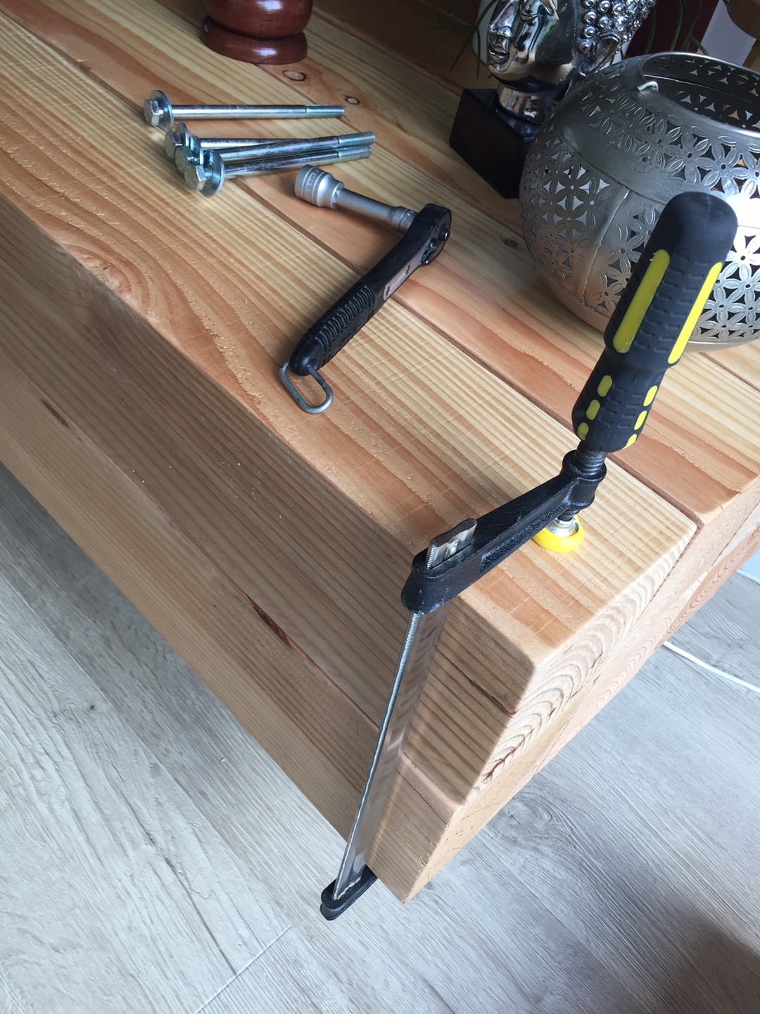
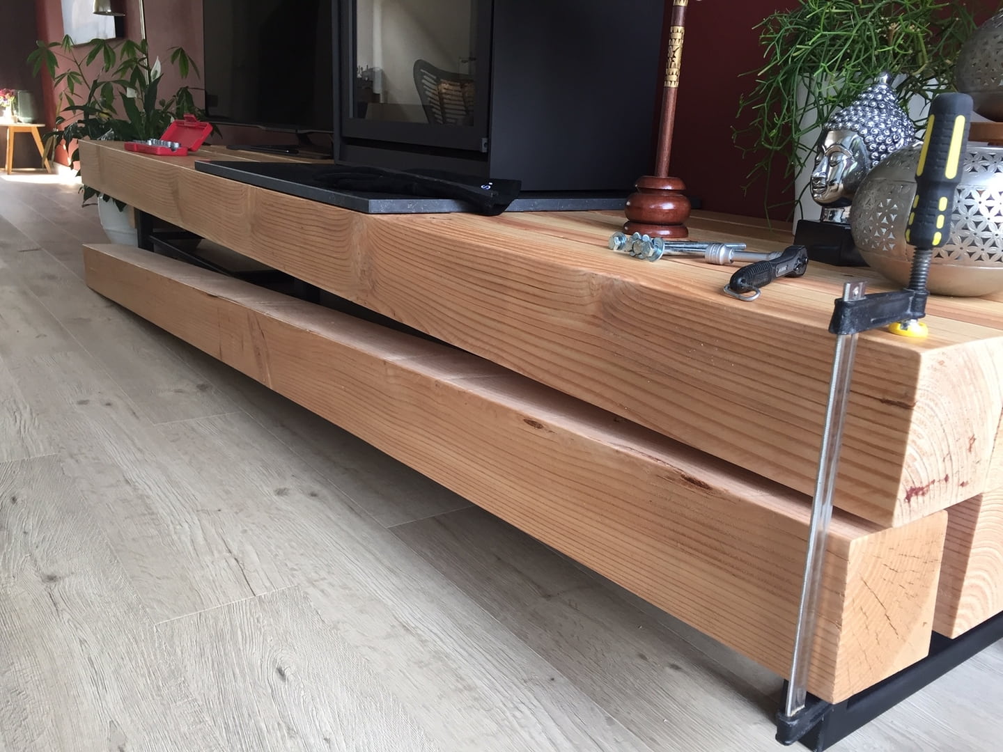
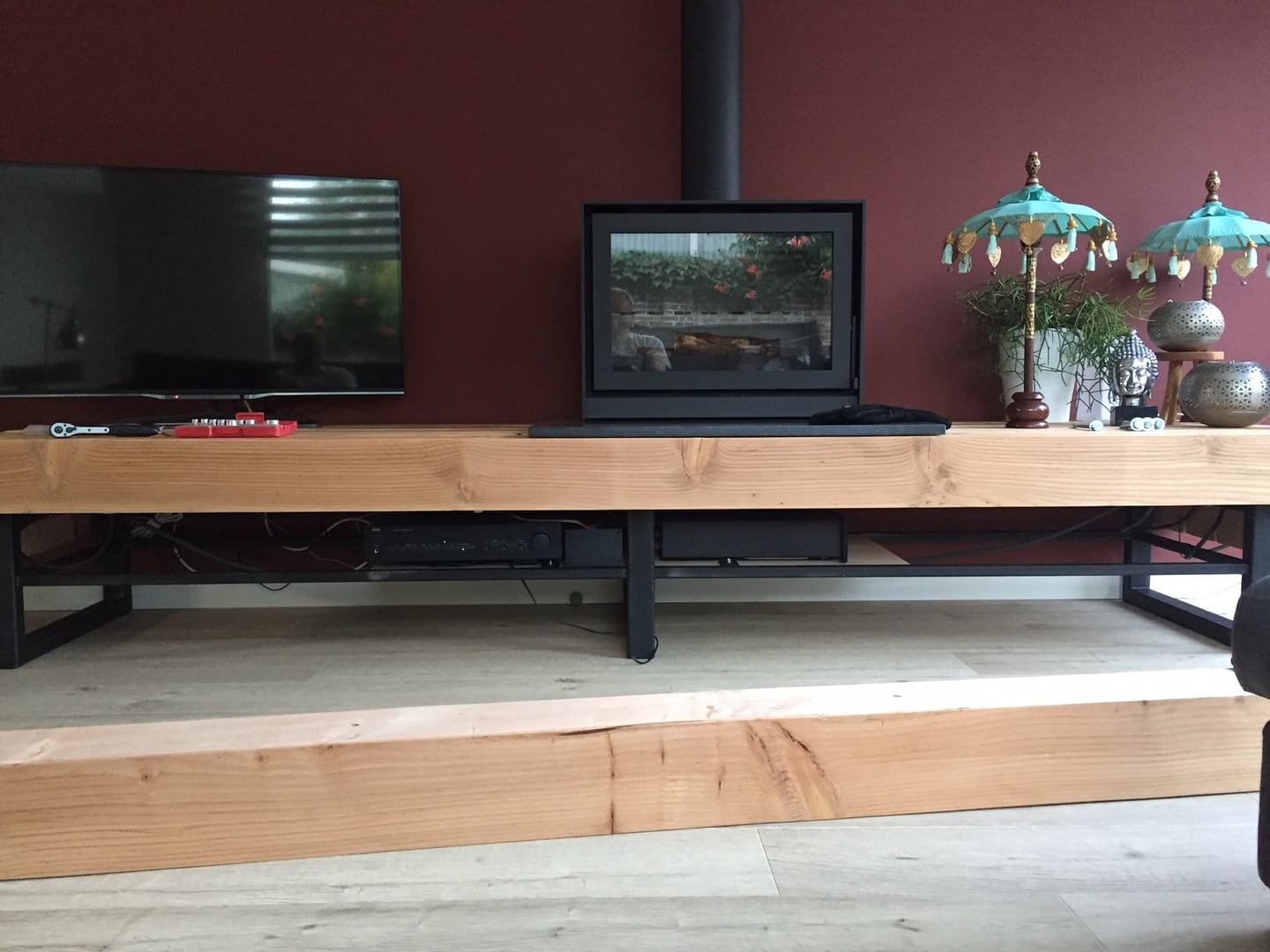
To add to my opening post I installed the equipment Friday evening which is now centered in the frame.
As earlier mentioned maybe a big single subwoofer would be best so then I better shift the equipment to the left and leave ample room for the subwoofer system.
Looking at it again I have a gross space of 160x50x20 cm = 160 litres ... should give me some options for subsonic frequencies
I know moest people are visual orientated (I know I am ) so here some pictures from the installation process:
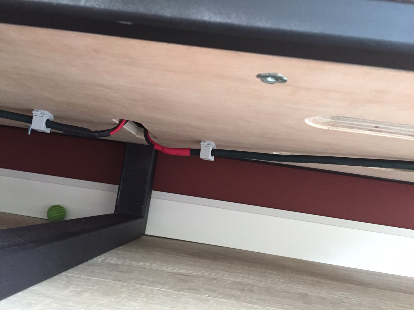
This is the way my wife likes it ... no visible equipment ... no visible cables ... and she thinks the W5"s are cute enough to be seen
The IR sensor installed at the center column ...
I have the standard W5 (not SE)
Thank you for the explanation, I will study it again and let it sink in ... acoustic behavior is not my specialty (I am an electronics engineer) but reading it carefully I guess I can draw some parallels to electronic circuits to understand the details.
@whgeiger
Thank you for the documents; I have not seen this review before but nice to read ... the subwoofer explanation is useful too to have
To add to my opening post I installed the equipment Friday evening which is now centered in the frame.
As earlier mentioned maybe a big single subwoofer would be best so then I better shift the equipment to the left and leave ample room for the subwoofer system.
Looking at it again I have a gross space of 160x50x20 cm = 160 litres ... should give me some options for subsonic frequencies
I know moest people are visual orientated (I know I am
) so here some pictures from the installation process:
An externally hosted image should be here but it was not working when we last tested it.
An externally hosted image should be here but it was not working when we last tested it.
An externally hosted image should be here but it was not working when we last tested it.
This is the way my wife likes it ... no visible equipment ... no visible cables ... and she thinks the W5"s are cute enough to be seen
The IR sensor installed at the center column ...
An externally hosted image should be here but it was not working when we last tested it.
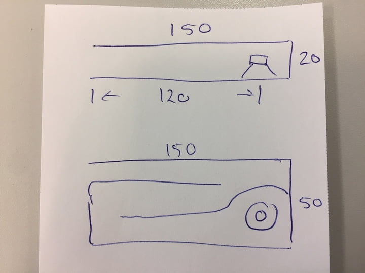
Please have a look at 3 possible scenario's that will fit in the steel frame:
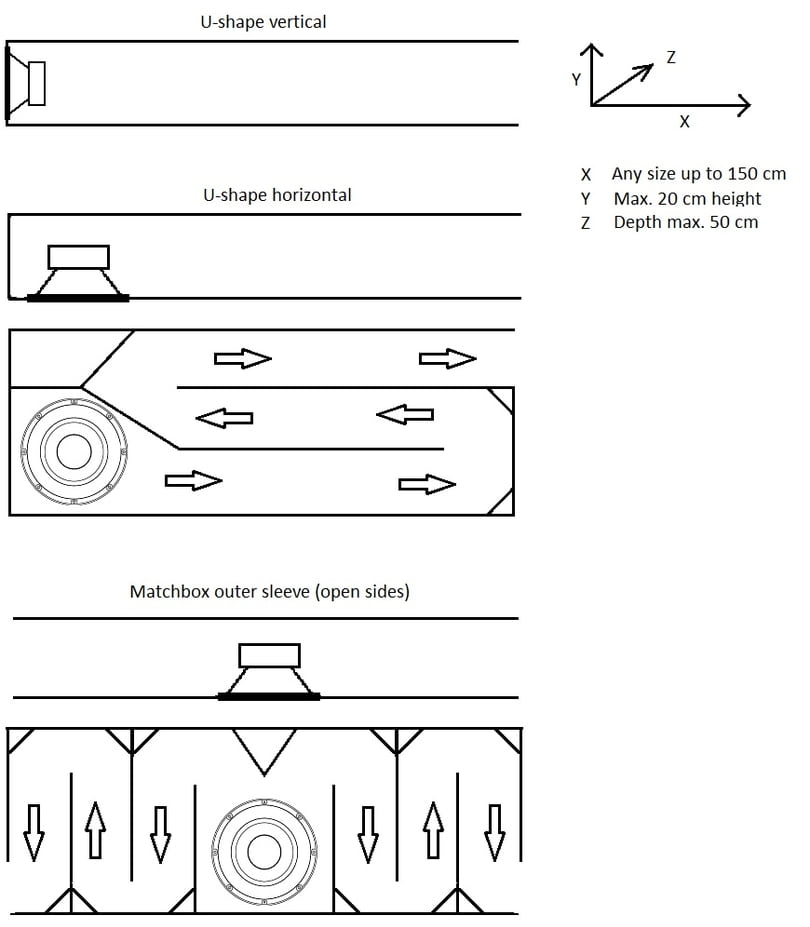
U-shape vertical: (side-firing woofer)
Not really interesting as the max. woofer size is limited by 20 cm external diameter which will not suit my LFE requirements no matter how well I design the cabinet ...
U-shape horizontal: (down-firing woofer)
Lots of options to place the woofer and design the interior.
Matchbox outer box style: (down-firing woofer)
Could this be something interesting ?
It has shorter dual-path to exit compared to U-shape but do I need the long paths anyway ?
Any other observations about layout and internal "channels" ?
In general I expect both horizontal positions to back-fire (literally) when the rear of the woofer is so close to the top panel ... would it be better to position the woofer angled (front of woofer towards listener) so that the rear refection is guided away from the woofer into the exit path ?
Expect that a suitable 12-15 inch woofer dimensions will have 15-20 cm depth so little room left behind the woofer/magnet.
Any other suggestions ?
P.S. if it would be beneficial to omit the channels and just simulate an open baffle why not ...
Last edited:
Hmm, with pipe end correction: ~34400/4/157.383 = ~54.644 Hz, though laying on the floor close to the wall drops it ~an octave, so ~27 Hz and driver has to be on the side to mount a decent size woofer. Driver specs Vs total pipe volume will determine how much gain potential it has, though at ~107 L net it won't be much.
The other two will take more time than I have ATM, but hopefully others will chime in.
GM
The other two will take more time than I have ATM, but hopefully others will chime in.
GM
Hmm, with pipe end correction: ~34400/4/157.383 = ~54.644 Hz, though laying on the floor close to the wall drops it ~an octave, so ~27 Hz and driver has to be on the side to mount a decent size woofer. Driver specs Vs total pipe volume will determine how much gain potential it has, though at ~107 L net it won't be much.
The other two will take more time than I have ATM, but hopefully others will chime in.
GM
Please realize the steel frame height is 35 cm so if I take 20 cm for the woofer cabinet attached to the underside of the wooden beams there is 15 cm left as space to the floor under the enclosure. This will visually hide the woofer for the "WAF" requirement.
I guess this is also relevant for the behavior of the sub ?
With the size limitation of 20 cm for a front-firing or side-firing I guess the down-firing sub is the only possible orientation to mount a decent size like 12-15"
The limitations of a fixed position / layout will probably create some challenges but I am looking for a clever solution to make the most out of it ... :D
- Home
- Loudspeakers
- Subwoofers
- Hidden subs (WAF requirement) design considerations