Why not create a tapped horn for the woofer?
TH = series BP6.
A straight flare single fold TH actually looks like a SBP6.
That would be an entire rebuild, which I'm trying to avoid at the moment. Also THs tend to be somewhat... large, and this sub needs to find under the bar's counter
")
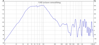
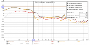
"Enigma 2", using the Dayton DA270 driver, raw response. +1,-3dB from 39 Hz to 120 Hz. Except for one or two minor peaks, all of the out of band noise is 20+dB below the passband, and the first (and most annoying) out of band resonance (around 400 Hz for this design) is significantly reduced.
I haven't finished working on the box yet (still have to experiment with lining the vented section, to see if I can get the out of band noise down even lower), but this looks very promising.
I haven't finished working on the box yet (still have to experiment with lining the vented section, to see if I can get the out of band noise down even lower), but this looks very promising.
Attachments
How does it sound to you?
I've only done some preliminary testing (I have to take the build apart again to work on the paint job and fix some other niggling issues), but it sounded pretty good.
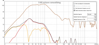
Distortion measurements also look pretty good, considering the limited Xmax of this driver, which suggests that it will start being noticeable @30W around 40 Hz (it definitely is not a subwoofer driver, LOL). Note that the THD is primarily 2nd order HD - the acoustic bandpass filter is doing a good job of keeping the higher harmonics down, and it looks like the box dimensions and layout are also nulling out 3rd order HD at 40 Hz. I could claim that was by design, but it's pure luck
Attachments
Note: the replacement driver does have an aluminum cone. That may provide a more efficient means for heat to exit the sealed section of the subwoofer cabinet than the previous driver's plastic cone.
No, it doesn't, at least not noteworthy. Unless membrane and VC are just one single piece or welded together (both extremely unlikely because very expensive and brings serious problems with it), the glue used to connect cone and VC acts as an insulator, the heat transfer is pretty bad. Someone tested it with an IR camera and the conclusion was it improved the heat dissipation by less than 3% and the basket was deemed to be much more effective but that strongly depends on the driver ofcourse. The site went down ~10yrs ago unfortunately and the images disappeared even before that. I hate it when the internet 'forgets' such informations.
So it looks like he just calculated it from the resistance.
Yes, and that's the real problem. Because the VC moves more or less depending on the music material/frequencies, it would be very important to know which parts of the VC are getting hot first since the average temperature doesn't matter because the weakest point failing is enough to stop the driver working. I've seen drivers able to do monster excursions burning out the VC in horns at a fraction of the rated power because they couldn't do enough excursion to cool the ends of the coil.
It doesn't make sense to me that the supposed source of heat (the voice coil) would be at a lower temperature than the sink (the magnet structure). Heat flows from hot to cold, not vice-versa.
That's actually correct. I was assuming the same but there are different mechanics in play, the heat transfer within a material, radiation, air movement as a cooling factor and the excursion. I'm not able to reconstruct the exact mechanics and all factors, it's really complex and too many parts of it are unknown to me and to be honest, I don't really want to start juggling with the equations at all either. But it's not my paper and nor was I the one bringing that up either.
It's still dissipating 100W - some into sound and the rest into heat
You are right but you didn't understand the point. On high ambient temperatures, it will not be able to dissipate nearly as much. High ambient temperature means, it cannot nor will dissipate the heat of 100W in such conditions! Meaning, the coil will burn up at even lower power!
As there is little space to invert the woofer, is transforming the enclosure to a parallel 6th order bandpass (both chambers vented to the outside world) an option?
The sealed part of the enclosure is extremely likely a lot too small to convert the sub to a 6th order BP, besides the enclosure volume, because the ports 'eat up' more of the chambers volume. That could be countered by a passive membrane but that eliminates the cooling through air exchange aswell.
Undersized vents actually aid in cooling due to turbulence.
That's correct, that is often actually utilized in a lot of PA speakers. The port shape and air velocity play a great part in that, ie. triangle shaped ports (edge ports, often used to save baffle surface/box size) even reduce the effective active port surface with too high air speed and turbulences in the edges and shifts the tuning frequency on such subwoofers noticable. That's also why some edge/triangle port double 15" (or other sizes too) sometimes sound different than the single/halved version of it. Part of it is the virtual extension of the ports in the edge vs. the ports on the side wall/middle of the baffle though. To shorten the ports is sometimes needed if single and double subs of the supposedly identical types are mixed.
As the current flow will be less when impedance is higher, IMO it's a non-issue. Hornresp suggests impedance is going to be around 27.5 ohms at the peaks. Box losses will likely bring it down to more like 18 ohms. Assuming a 28.3V input, that works out to 44.5W (1.57A), well within the driver's rated capability, and way below where I want the breaker to trip.
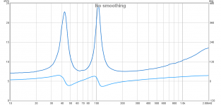
Looks like I built this box well. The impedance peaks are 22.8 ohms and 24.3 ohms. There's likely a way to estimate the box losses from the difference between the sim'd and actual impedances, but I don't know how to do this. In any case, this means that the driver is only going to see 35W and 33W at those frequencies, if driven with at 100W amp.
Minimum impedance in the passband is 7.62 ohms however, which translates to 105W at that frequency (around 64 Hz), where cone movement is going to be at a minimum. Hmm...
Assuming that I get the rest of the work on the box done over the next few days, I'll be able to do some sine sweeps at different voltages on the system this weekend. Basically checking to see how the output changes with input voltage. The sine sweeps are just over 5 seconds long. Let's see if I can get that breaker to trip...
Attachments
Last edited:
I think it just depends on what the driver was design to do. The DA270 driver was designed for use in 3 way systems, not really for subwoofer use. Compare to the RSS265 driver from the same manufacturer - that was designed for subwoofer duty and it's an aluminum cone driver with a 2.5" voice coil. The DA270 has a rated power handling of 70W, and the RSS265 has a rated power handling of 600W.
Looks like I built this box well. The impedance peaks are 22.8 ohms and 24.3 ohms.
I don't doubt your box works fine but the almost equally high impedance peaks do not imply it works well. In the old days it was a rule of thumb the two peaks had to be almost of the same height, nowadays there are tons of speakers which divert from that rule and work very well too. Back then it was an easy way to approximate how a speaker (sub) works since the fast Fourier transformation could not be applied because of lack of processing power and a correct low frequency measurement was impossible for most folks because of the requirements of the measurement (nearest reflection surface, measurement distance and room modes/influences). A lot of non-equal-height-impedance-peak speakers sound great and there are quite some speakers which fulfill the equal height impedance rule but sound awful. In reality this rule applies only to a narrow range of Qts/Qt (~Qb3 ideal) and can divert a LOT from that to get great results since the room gain and frequency response is different for every setup and room and personal taste.
There's likely a way to estimate the box losses from the difference between the sim'd and actual impedances, but I don't know how to do this. In any case, this means that the driver is only going to see 35W and 33W at those frequencies, if driven with at 100W amp.
AFAIK WinISD pro is capable of simulating it as long as you stay within the low loss port air velocity range.
Minimum impedance in the passband is 7.62 ohms however, which translates to 105W at that frequency (around 64 Hz), where cone movement is going to be at a minimum. Hmm...
As I already said, it's not the total power nor the current which is critical, it's the heat dissipation capabilities which count - which are dependent on the ambient temperature and the air exchange and the frequencies. There is no way of limiting it to a 'safe range' if you are trying to limit just ONE parameter (current) since it DOES NOT represent at all what temperatures are actually reached at the VC. Ambient temperature and airflow are much more important for that limit to divert vastly. I've driven 4 15" subs in winter outside with ~500W each and they performed perfectly while a friend used my subs at a summer party and with just ~150W each, two died. I cannot stress it any more, the enviroment is crucial! Thermal design does not depend on just one single parameter.
Assuming that I get the rest of the work on the box done over the next few days, I'll be able to do some sine sweeps at different voltages on the system this weekend. Basically checking to see how the output changes with input voltage. The sine sweeps are just over 5 seconds long. Let's see if I can get that breaker to trip...
That breaker won't do sh*t (or trigger way too early), depending on the enviroment. If you want to be safe, either use a DSP with peak and rms limiter or measure the pole plate temperatures to stay within the parameters the driver can cope with.
I don't doubt your box works fine but the almost equally high impedance peaks do not imply it works well.
That's not what I was using as my point of reference. My point of reference is the magnitude of the impedance peaks predicted by the sim, which assumes no losses. The closer the measured impedance peaks are to the sim, the less "lossy" the box is.
As I already said, it's not the total power nor the current which is critical, it's the heat dissipation capabilities which count - which are dependent on the ambient temperature and the air exchange and the frequencies.
Yup, and the more power the driver has to dissipate, the more critical those heat dissipation capabilities. That's why I HAVE to take the power the driver may see into consideration. And yes, it IS critical. If I was running the equivalent of 5W into this driver, we wouldn't be having this conversation ;-).
that's pretty impressive. What from this experiment might be applied to other builds?
For a 4th order BP design, use the largest vents that you can, and design the layout such that the position of the driver nulls out the lowest (and most problematic) peak in the out of band noise?
Seriously, there's a reason why I call this particular build the "Enigma". It was built long before I started using Hornresp, and it constantly defies any of my attempts to successfully model it in Hornresp (well, apart from the offset driver thing, which did predict the nulling out of the first out of band response peak).
Case in point: The "Enigma" currently has two flared 3" vents, that have an effective lengths around 21 cm each. The Hornresp modeling that I did for the replacement driver suggested that I'd have to cut the vents down to 14 cm each, which would boost Fb to 71 Hz and flatten the passband. Well, it's a good thing that I decided to do some measurements before proceeding to cut the vents, because the results suggest that, if anything, the vents may already be slightly too ***short***, even though they're a good 50% longer than what the model suggests should be used! Fb is around 64 Hz instead of 71 Hz, but the passband shows a slight upwards instead of downwards tilt. And no, I don't know why this is happening. At least, not yet. I plan to take a much closer look this weekend, to see if there's something that I'm missing.
Brian, which (if any) free spreadsheet programs will run your horn fold sheets in Windows?
Unfortunately, I don't know of any offhand.
I had an opportunity to do a few more power tests this weekend. Some notes:
I used my car's 1.2kW (into 4 ohms) amplifier to do the testing, as my usual test amplifier was not available. I had to add 8dB of gain at the deck to achieve 23.3V at the deck's volume setting of 40, my usual volume setting (unless it's the weekend). This is interesting, as that means that at the amps' normal gain setting, my car's two 12" subwoofers that present a combined 2 ohm load to the amplifier would only be seeing about 43W total, or about 21.5W each, if my calculations are correct. No wonder my car's system seems to have so much headroom at bass frequencies...
- I was able to driver the subwoofer with up to 23.3V until measured distortion got over 10% in the passband. The THD significantly increased below this (as predicted by the sim'd driver excursion). Going by the distortion graph, a 30~35 Hz 12dB/oct HP filter will increase the subwoofer's power handling as far as THD is concerned.
- 23.3V works out to about 68W into 8 ohms, or 70W into the subwoofer's measured minimum impedance in its passband. Current draw at that impedance works out to 3A.
- The subwoofer's output remained very linear right up to that distortion limit. I suspect that this is one of those bandpass builds that sounds very good at higher and higher SPL levels - until you don't hear any sound at all, LOL. Who says that small signal parameters produce sims that are only accurate at small signal levels?
- Leaving the amp's gain at the point where it was generating a 23.3V sine sweep, the subwoofer played back a wide selection of music for about two hours without showing any audible signs of distress. It was also loud enough to provide background level music at the bar IMO.
- The inline PTC did not trigger during the testing. I suspect that was due to the length of the sine sweep test signal, which was not long enough (the PTC device needs to see double the rated current for at least 5 seconds before triggering). It also did not trigger during the music testing.
I used my car's 1.2kW (into 4 ohms) amplifier to do the testing, as my usual test amplifier was not available. I had to add 8dB of gain at the deck to achieve 23.3V at the deck's volume setting of 40, my usual volume setting (unless it's the weekend). This is interesting, as that means that at the amps' normal gain setting, my car's two 12" subwoofers that present a combined 2 ohm load to the amplifier would only be seeing about 43W total, or about 21.5W each, if my calculations are correct. No wonder my car's system seems to have so much headroom at bass frequencies...
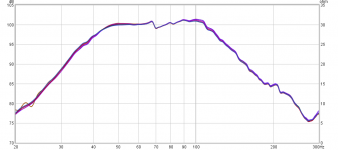
...and here's what the THD looks like (normalized to the FR) at 23.3V. Even at that level it remains around 1.2% from 50 Hz up. Below that the driver's excursion starts to have an impact, and at 39 Hz it's at 10%. That's why I think at 30~35 Hz HP filter should help reduce reduce distortion and increase mechanical power handling, if necessary.
Those little bumps just about 160 Hz? There's something buzzing inside the enclosure at high input levels. I haven't figured out what it is yet. It's quite a bit outside of the subwoofer's useful passband in any case.
Those little bumps just about 160 Hz? There's something buzzing inside the enclosure at high input levels. I haven't figured out what it is yet. It's quite a bit outside of the subwoofer's useful passband in any case.
Attachments
Just a quick update to this ongoing saga:
I installed "Enigma v2" in my brother's bar just over a week ago, where it sees somewhere between 8~12 hours of continuous play every day. I also replaced the Technics receiver with a Monoprice Unity 200 amplifier to drive the main speakers (100Wx2) and a Monoprice Unity 100 to drive the subwoofer (100W bridged into 8 ohms). Both amps feature only a power button on the front panel, so they are quite fiddle-proof, something that was needed for this bar.
Feeding the amps is a Dayton DSP408, which provides the filtering and EQ needed. For the sub, a HP filter at 30 Hz (to reduce distortion at low frequencies at higher SPL levels) and a LP filter around 150 Hz (to eliminate out of band noise). I didn't have my measuring equipment with me, so I basically adjusted the gains by ear, to ensure that the DSP408 overloaded just before the amps did, to ensure that the speakers were not over-driven. I might go back in a week or two to fine-tune the gains of the amp and DSP.
Feedback from my brother: "Brian last night I went to the bar and the bar system ( the laptop was not working ) but Kingsley hooked up his phone and damn! Bro that system in the bar is off the chain that is the best I ever heard it sound. Not loud ( even though he could go loud) but real clean with a nice low bass."
So, mission successful, so far.
Will the subwoofer hold up under long-term use? Well, it's only been a week, but it has been used every day of that week for fairly long periods. If it doesn't blow first, I'll do an impedance check on it in a few months to see if there's been any change.
- Home
- Loudspeakers
- Subwoofers
- Rebuilding the Enigma...