That is the trick of MFB stability. You have to attend to the phase well outside the bandwidth of interest if you intend to use more than a few dB of loop gain to combat distortion.…Phase sure is an issue with speakers that have resonances within their bandpass. But if we are aiming only for 20-200 Hz*, the phase margin stays within about 90-degrees. Funny stuff outside that band is tolerable or manageable, so long as there's no oscillation…
Can you clarifiy your question?But is the phase trace more favourable with current feedback?
Are you asking about using negative current feedback to implement current source drive of the woofer?
If so, HF stability is certainly a challenge. Section 4 of the RMS Whitepaper #6 has a description for one recipe that results in a stable current feedback setup. However, it does require use of a power amplifier with first order roll-off at its upper bandwidth which is often the case, but not always.
http://rmsacoustics.nl/papers/whitepaperMFBdesign.pdf
Thanks so much for sharing. This looks like a good setup, providing very nice LF capability.The StarBass V/2P as used by Rob follows this schematic:
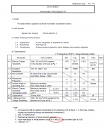
Most likely the measurement setup used had a lower input impedance than 39M, and of course a single sensor instead of two which would raise the roll-off frequency by an octave. I see mention on their website of a 10M input impedance being used, but it was not specifically associated with the plot in the other data sheet.The Murata PKGS-00LDP1-R shocksensors typically have an capacitance of 0.7nF making a total of 1.5nF for the /2P variant Rob is using. R2 is set to 39M resulting in a lower pole of 2.72Hz. The FR on page 3 of the datasheet looks disturbing with output decreasing below 20hz already but doesn't seem to effect the usage of the sensor as accelerometer sofar.
https://www.murata.com/en-us/products/productdata/8797617029150/00LDP1-E.pdf
Attachments
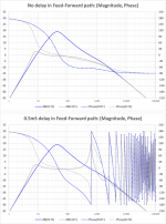
The service manual shows the input circuitry is DC coupled, so the LF roll-off is coming from something in the power-amp portion of the circuit, so not sure if it would be as easy to improve it or not. That said, the Inuke 3000 should do fine for MFB, with LF roll-off -3dB @ 4Hz. The DSP version of the Inuke 3000 be avoided because of the the resulting delay in the feedback loop. Even 0.5mS of delay will cause HF stability problems unless you loop-gain is low. Berhinger and MiniDSP products have latency in the 2mS to 3mS range.…would Inuke 3000 work with Current feedback, and MFB?
Or do i have to mod input filter cap to extend the phase margin?
When you are asking about current feedback, I am assuming that it is related to converting the inuke into a current source as detailed in the RMS whitepaper? If so, I don’t think it would be a good candidate because it lacks the recommended first order roll-off at HF that the Hypex modules inherently have.
Attachments
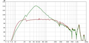
That is interesting, especially since the large peak was suggesting extremely small phase margin which didn’t seem to match up with the gain or filters you were using. That was one of the reasons I had asked chriscam about the LF capability of the sensor.…Note the relative absence of the 11 Hz resonant peak that appears in previous posts. This is interesting because it cannot be fully explained by the addition of the relatively gentle high-pass filter. Maybe this was largely due to the measurement setup previously used in the workshop?
Can you describe the difference in measurement setup?
Is it possible the workshop had a room mode down in that range? (That might also explain the notch we though might possibly be attributable to the microphone.)
Back to back measurements with and without the MFB path closed as chriscam suggest would be helpful to determine the open-loop transfer function.
That is interesting, especially since the large peak was suggesting extremely small phase margin which didn’t seem to match up with the gain or filters you were using. That was one of the reasons I had asked chriscam about the LF capability of the sensor.
Can you describe the difference in measurement setup?
Is it possible the workshop had a room mode down in that range? (That might also explain the notch we though might possibly be attributable to the microphone.)
Back to back measurements with and without the MFB path closed as chriscam suggest would be helpful to determine the open-loop transfer function.
The electronics were unchanged, but the rooms and position of the speaker within them were different. In the workshop, the speaker was sitting up on a WorkMate table. This was facing my main workbench on which was sitting the tripod with microphone. The first room mode in the workshop might be around 30 Hz as it is a smaller room. The speaker would have been a little off centre in the room in X and Y axes and about centre in the Z axis. In contrast, the speakers were only about 16" off the floor in the listening room as shown in the last photo and about 1/4 of the way into the room in X and Y axes.
I'll make the requested measurements tomorrow.
They do, but heavy woofers don’t make good microphones so there is minimal interaction.… I've been wondering forever how MFB (which resembles active room acoustic control) interacts with room modes? The room modes must act on the cone like any other error.
The AVAA product that chriscam linked to is a nice bit of engineering. It is not trying cancel out pressure waves, rather it is generating a matching acoustic impedance so that the waves are not reflected…same concept as terminating a transmission line in its characteristic impedance. Similar to Ohms law(R = V/I), the acoustic impedance is the ratio of local applied pressure to the resulting local particle velocity. A microphone is used to measure the pressure and then the woofer is used to adjust the local velocity to achieve the target acoustic impedance to minimize acoustic reflection that sustains room modes. There has been ongoing research on this concept over the past 15 years with dozens of papers and thesis documenting the progress. Most papers are too big to post, but you can access one of the AES convention presentations that is linked to at the bottom of this review page. PSI Audio Active Velocity Acoustic Absorber C20
Two implementation methods have been patented in Europe, but it seems not in the US…probably because of the similarity to the Olson patent and his JASA paper. (See Figure 4 in the patent, Figure 14 in the JASA paper)
Attachments
Ten-thousand (more) "thank you"'s for explaining, esp about the the PSI secret mic, eh....A microphone is used to measure the pressure...
It's worth looking at the Olson patent just for the pictures (esp the weird guy in the comfortable chair). Great pictures in his textbook too.
I can see the possibility of using a mic as sensor for low freq absorption, while not feasible for MFB applications.
But feedback theory not withstanding, you'd think cone motion (in a dedicated absorber or in an MFB sub) would be adequate for absorption purposes with enough loop gain, even if a cone is a poor mic/sensor.
If so, rscamp's speakers should show some room mode corrective action? But a puzzle to me how you'd demonstrate that independently of general MFB action - other than changes to the far-field acoustic trace?
If a MFB sub can be designed to have a material influence on room modes, that makes it a very major advance in music reproduction, vastly more important than trivial changes like baffle step correction.
B.
Last edited:
Better use lots of small drivers in parallel thenThey do, but heavy woofers don’t make good microphones so there is minimal interaction.
") on a side note, I find Bob Katz his statement It’s amazing the precision, beauty, tightness and control of the bass in my mastering room typically the kind of description people give when witnessing a well designed servo system for the first time. Which makes me wonder
on a side note, I find Bob Katz his statement It’s amazing the precision, beauty, tightness and control of the bass in my mastering room typically the kind of description people give when witnessing a well designed servo system for the first time. Which makes me wonder Ten-thousand (more) "thank you"'s for explaining, esp about the the PSI secret mic, eh.
It's worth looking at the Olson patent just for the pictures (esp the weird guy in the comfortable chair). Great pictures in his textbook too.
I can see the possibility of using a mic as sensor for low freq absorption, while not feasible for MFB applications.
But feedback theory not withstanding, you'd think cone motion (in a dedicated absorber or in an MFB sub) would be adequate for absorption purposes with enough loop gain, even if a cone is a poor mic/sensor.
If so, rscamp's speakers should show some room mode corrective action? But a puzzle to me how you'd demonstrate that independently of general MFB action - other than changes to the far-field acoustic trace?
If a MFB sub can be designed to have a material influence on room modes, that makes it a very major advance in music reproduction, vastly more important than trivial changes like baffle step correction.
B.
I don't think an MFB speaker itself is going to act as an absorber. At the frequencies of interest, the external influences would be opposed by the MFB control and the driver would act like a rigid wall. To be an absorber, the driver should move WITH the air particles to mimic an open window. But if it used an external microphone as the above examples, the better MFB control of the driver should make it a better absorber.
Last edited:
...the driver would act like a rigid wall. To be an absorber, the driver should move WITH the air particles to mimic an open window....
You're right about the astonishing rigid wall feel of MFB. But I can't figure out if I should apply wave physics or quantum mechanics here?
B.
Back to back measurements with and without the MFB path closed as chriscam suggest would be helpful to determine the open-loop transfer function.
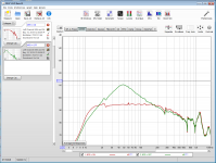
I'm having a busy week, but I did a quick grab for the left (no damping material) channel. I included an image below but the REW file was too large to post here. PM me an email address and I can provide a shareable link to the REW file.
Attachments
Thanks for the REW file.
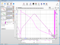
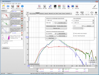
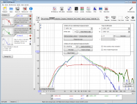
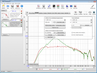
Here are the steps to calculate the OLTF which is needed to determine phase margin.
Step 1: Label the two measurements appropriately and then click on the [All SPL] tab.
Step 2: Click the "Controls" icon to bring up the dialog box to perform arithmatic
Step 3: Load the "MFB=OFF" measurement into slot A, the "MFB=ON" into slot B, select the arithmetic operation "A-B" and then click the [Generate] button
Step 4: Load the "A minus B" result you just generated into slot A, change the arithmetic operation to "A/B" and then click the [Generate] button
Step 5: Switch to the [SPL & Phase] tab, select the Final result generated in Step 4 and adjust the scales appropriately to be able to comfortably view and identify the phase at zero dB crossing with the cursors.
Looks like you could increase loop gain about 5dB and still have an acceptable 30deg phase margin. I will take a look this weekend to see if there is any minor changes in filter components that would improve this phase margin further.
Attachments
I don't think an MFB speaker itself is going to act as an absorber... the better MFB control of the driver should make it a better absorber.
I woke up with this very very obvious decision strategy insight: try it.
Put the MFB speaker in one corner and another speaker in another corner. For greatest test sensitivity, put the mic near the centre of the room.
BTW, we've all seen links to YouTube demo's where you're supposed to hear how great a new tweeter is by listening to the demo on your laptop's speaker. But, not the same idiocy recording an MFB demo for YouTube because the benefits should be hearable A/B. (Maybe not the test suggested in this post which requires comparing two freq curves).
B.
Last edited:
I woke up with this very very obvious decision strategy insight: try it.
Put the MFB speaker in one corner and another speaker in another corner. For greatest test sensitivity, put the mic near the centre of the room.
BTW, we've all seen links to YouTube demo's where you're supposed to hear how great a new tweeter is by listening to the demo on your laptop's speaker. But, not the same idiocy recording an MFB demo for YouTube because the benefits should be hearable A/B. (Maybe not the test suggested in this post which requires comparing two freq curves).
B.
One thing to consider with this I suppose is that well below the Schroeder frequency most of what we hear is modal. With the speakers in opposing corners, the microphone in the centre would be at the null for the first plan view modals - the lowest frequencies that are well supported by the room. In a way, these are the most interesting frequencies to compare between MFB and passive subwoofers as the MFB benefits would be greatest. If the room is near square in plan view, almost nothing would be heard by the microphone in this position at the first modal frequency.
One thing to consider with this...
The test(s) are now in good hands.
I'd say to start, you want the test of principle to have every advantage just to see if it works even a little.
Seems a straight-forward FR test, no conceptual choices to speak of. Should take minimum time to do the runs if you have one MFB sub (esp in a corner) and any other sub that plays low (esp in a corner).
B.
If sensor = mic, then you need a specific level of loop gain(more is not better) to get local cancellation of the pressure.… you'd think cone motion (in a dedicated absorber or in an MFB sub) would be adequate for absorption purposes with enough loop gain, even if a cone is a poor mic/sensor.
This is how the Bag End E-trap works, and why its adjustment knobs must be fiddled with while watching REW type sweeps in real time.
If sensor = accelerometer, remember increasing loop gain increases the effective moving mass, easily over 2kg in most MFB systems. The air pressure “error” is just not going to have much effect on the woofer acceleration, hence why I had said minimal interaction. As rscamp mentioned, any interaction there is would be in the direction to enforce the pressure not cancel it.
You might find it interesting that woofers can make reasonably good passive absorbers with appropriate electrical loads added to their terminals. The effective bandwidth is limited though. This was actually what several of the AVVA developers started out researching before switching to an active approach. (example paper attached)
Section 2 of the Rivet Thesis has thorough treatment of this type of absorber.
https://infoscience.epfl.ch/record/222866/files/EPFL_TH7166.pdf
In laboratory type setups, tubes are used with the absorber device at one end and source at the other.… a puzzle to me how you'd demonstrate that independently of general MFB action - other than changes to the far-field acoustic trace?
Then you can easily measure and quantify how well the end reflections are absorbed across the bandwidth of interest.
As you suggested, measuring or listening to other sources in a room while an absorber device is added or removed from the room works as well, although the 3 dimensional aspect of modal behavior makes the results less clear unless you have an array of microphones. The research/developers of the AVAA include many room measurements in their papers and a few audio clips(real kick drum and recording of string bass played thru subwoofer) in their presentations. I extracted some charts and sound clips from one of their larger presentations. Pretty amazing what just a few actively controlled 6” drivers can do to damp a 200m^3 unfurnished room. They look insignificant sitting in the corner…only 0.1% wall coverage according to the presentation. Note that besides frequency response/waterfall plots, they also consider RT60 type decay measurements to be a good indication of how much audible improvement will be perceived.
Attachments
Last edited:
Microphone based active sound absorber want to neutralize the soundpressure, so when the pressure rises the cone will move inwards trying to keep the pressure at 0.
MFB works the opposite 180deg, when the pressure wave hits the cone MFB will push back and keep the cone stiff.
So they work in opposite I would say.
MFB works the opposite 180deg, when the pressure wave hits the cone MFB will push back and keep the cone stiff.
So they work in opposite I would say.
Reading several papers on MFB, it seems ika that there is a benefit of driving the elements with Current FeedBack amplifier or CFB.
Found following amplifier on ebay that I want to try with my Dipole CFB/MFB subwoofers.
Hi-End Improved ACCUPHASE A60 Stereo Amplifier,DC Current NFB,Doubled Transistor | eBay
It will drive 3xDayton IB 15" elements in parallell, giving 2,5 Ohms load..
Found following amplifier on ebay that I want to try with my Dipole CFB/MFB subwoofers.
Hi-End Improved ACCUPHASE A60 Stereo Amplifier,DC Current NFB,Doubled Transistor | eBay
It will drive 3xDayton IB 15" elements in parallell, giving 2,5 Ohms load..
1. Eliminating motor related distortion you will need current drive.
2. Eliminating suspension related distortion you will need MFB.
3. Eliminating cone break up related distortion, live with it or try to design the golden egg.
Point 1 can't live without 2 because the lack of damping factor.
Just buy some Hypex gear, completely stable in a current setup.
2. Eliminating suspension related distortion you will need MFB.
3. Eliminating cone break up related distortion, live with it or try to design the golden egg.
Point 1 can't live without 2 because the lack of damping factor.
Just buy some Hypex gear, completely stable in a current setup.
- Home
- Loudspeakers
- Subwoofers
- MFB for ACI SV12 Drivers using Piratelogic Electronics