I never suggested you weren't!I'm quite familiar with how a loudspeaker works.
My statement, 'Look at how a speaker works', was simply an introduction to the physics which followed.
")
I'll have a look at your physics and get back later.
The point I was making was that the action and reaction forces are equal in size regardless of the ratio of the action and reaction masses.So that would translate to higher velocity when the mass is lower, to compensate and be equal in force.
It is the primary fact that the forces are equal in size which dictates the secondary fact that the smaller mass has the greater initial velocity.
I obviously need more information on 'mass compensating'!
Pairs of forces will sum to zero if they are equal and opposite and act on the same object.All we want is sum(F) = 0.
I was considering the action force on a loudspeaker cone and the reaction force on the magnet which do not sum to zero since they act on different objects.
So we need to make it clear on which objects the forces are acting.
You appear to be talking about an interaction beween the woofer and the tactile transducer and I will now have to get my head around how the distribution of force and mass results in 'force cancelling' or 'vibration cancelling'. Any further illustration would be welcolmed!
P.S. The force between the voice coil and the magnet provides the fundamental source for the force transferred to the cabinet, so it's not really true to say that we don't particularly care about the magnetic force!
Pairs of forces will sum to zero if they are equal and opposite and act on the same object.
I was considering the action force on a loudspeaker cone and the reaction force on the magnet which do not sum to zero since they act on different objects.
The force generated by F=BIL will act on both the cone and the magnet equally. The magnet is much heavier, and therefore undergoes smaller accelerations than the cone.
When you've bolted the magnet to a rigid enclosure, the mass of the magnet effectively increases, so the accelerations get even smaller.
So we need to make it clear on which objects the forces are acting.
We want to use a tactile transducer to null cabinet-borne vibrations. If you assume a rigid cabinet, it won't matter much where the tactile transducer is mounted.
Let's take an example.
This will be fairly real-world, in that the driver I'm talking about is sat here in front of me.
At 20.15Hz, the diaphragm undergoes a peak acceleration of 180.6m/s^2. Since the moving mass of the diaphragm is 126.5g, we can work out the peak force involved:
F=ma=0.1265*180.6=22.85N.
When that force is applied to a 50kg cabinet (Newton's Third Law), a=F/m=0.457m/s^2.
It's that acceleration that we want to cancel.
Chris
So you'd essentialy have to ignore the sound, and do a sweep measurement on vibrations using not a microphone, but a g force sensor.
After measuring the sub you'd have to measure the tactile transducer the exact same way, apply eq through dsp, make sure the phase is 180 degrees relative to the sub, and then you're set.
Anything else?
After measuring the sub you'd have to measure the tactile transducer the exact same way, apply eq through dsp, make sure the phase is 180 degrees relative to the sub, and then you're set.
Anything else?
As hinted at by Chris earlier, the enclosure vibrations would not be a simple analogue of the woofer vibrations, but would include the enclosure resonances.Anything else?
Therefore I agree that, in order to construct an accurate compensating signal for the tactile transducer, the cabinet vibrations must be monitored by a sensor.
I think somehow this changed into something else in terms of oscillation.
Hypothetical...
I have cabinet, a driver, and shaker.
Driver is on right side. Cabinet oscillates left and right due to driver forces. Shouldn't the shaker be opposing the driver on the left side to minimize the shake of the system? I don't see how mounting it on/in another position will help mitigate much of anything. I am not talking of cabinet wall flex, but it might affect the dispersion of the forces involved.
I have re-read TBTL's post which suggests there is no need to compensate for cabinet resonances, but only for the 'rigid body' vibrations. It appears I have to retract my musings in post #27!It does not matter that much as you are only controlling the rigid body motion of the enclosure. Modes for which the enclosure is flexible are at frequencies above the pass band of a subwoofer.
In accord with wolf_teeth's question in the previous post, I would be interested to know where the tactile transducer is positioned for effective vibration cancellation in the Sunfire SubRosa wall mount subwoofer mentioned by TBTL in post #6.
The SubRosa uses an IBEAM transducer mounted to the front baffle between the two woofers.… I would be interested to know where the tactile transducer is positioned for effective vibration cancellation in the Sunfire SubRosa wall mount subwoofer
See attached pics, and IBEAM info at: Sonic Immersion VT200 IBEAM Vibro Tactile Transducer Bass Shaker
Attached also are Carver’s patent for the SubRosa, earlier Sony patent on essentially the same idea, and the IBEAM patent.
As mentioned in the Carver patent, “…the tuning of the drive for the inertial mass is synchronized with the speakers so that the phase, amplitude and frequency of the movement of the inertial mass or masses matches that of the two speakers…” In other words, to work properly the resonance and Q of the tactile transducer must match that of the woofers. Most tactile transducers are fairly high-Q, so you will need to modify it, or select an appropriately high-Q woofer in a small box and perhaps fine tune resonance by adding mass to one or the other. Of course you would need EQ to flatten/extend the response as desired. If you plan to drive the shaker from a separate amplifier, you can just use a Linkwitz Transform EQ to match the shaker fs and Q to the (woofer+box) fc and Qc.
Attachments
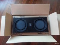
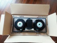
Thank you for your comprehensive suite of information.The SubRosa uses an IBEAM transducer mounted to the front baffle between the two woofers.
The photos satisfy my immediate curiosity and I've flicked through the pdfs which will take more time to take in and understand fully!
No matter what i do it gets wasted as vibrating stuff all around outside of the box and in it. Once its a solid rigid stressed in opposition and preloaded even, its just the next... and thats an endless cycle long after its left the ‘box’. Now i want to mske the box heavy and couple it to the fireplace, the vehicle or the atmosphere or air molecules. I can't win, no matter what..
But something unique happens when the air columns lengths are broken up too... its part of another piece of the pie?? PI!!!!
What if humming/ blowing air or another driver played into the vent creates a resonance on the cone? and that is one which you can identify?
Mass velocity is still part of the game. As cone mass/ air mass/ pressure (as a force over area )(mass against that mass)... the cone feels a mass as VAS, (CSA). pipe as 3 slugs of air between nodes/antinodes and two as it can be 4 or 5 pipes 5:2,1.5:1, 3:1,4:1... or 7. Whatever, but:
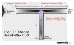
Dead end
Air column
Driver/fold
Air column
Fold(dead end/direction swap)
Air column
Exit/ junction to antinode/sacrificial pipe/fold/dead end
Air column
Driver/fold
Air column
Dead end.
You bounced out a sine wave shape at its most important parts from either direction as the same phase as the other. And that 90 degreees missing in a qw pipe?
Strong motor and lower Fs and mediocre Q(0.35-0.55)? Kinda makes for a ‘small’ (LOL) enclosure if Vas isnt too much?
18” <240
15” < 120
12” <60 liter
10” <30
8” <15
6”<5...
.....
Spitballing but not without reason(?)??
This is probably obvious to many people bit why does it make such a great impression on the listener and sometimes destroys the room? But this is even worse, i have cone control and can push that driver deep or loud or all of the above if i find the perfect CSA and Bl^2/re its like Donkey Kong is punching or steam rolling the waves??
But something unique happens when the air columns lengths are broken up too... its part of another piece of the pie?? PI!!!!
What if humming/ blowing air or another driver played into the vent creates a resonance on the cone? and that is one which you can identify?
Mass velocity is still part of the game. As cone mass/ air mass/ pressure (as a force over area )(mass against that mass)... the cone feels a mass as VAS, (CSA). pipe as 3 slugs of air between nodes/antinodes and two as it can be 4 or 5 pipes 5:2,1.5:1, 3:1,4:1... or 7. Whatever, but:
Dead end
Air column
Driver/fold
Air column
Fold(dead end/direction swap)
Air column
Exit/ junction to antinode/sacrificial pipe/fold/dead end
Air column
Driver/fold
Air column
Dead end.
You bounced out a sine wave shape at its most important parts from either direction as the same phase as the other. And that 90 degreees missing in a qw pipe?
Strong motor and lower Fs and mediocre Q(0.35-0.55)? Kinda makes for a ‘small’ (LOL) enclosure if Vas isnt too much?
18” <240
15” < 120
12” <60 liter
10” <30
8” <15
6”<5...
.....
Spitballing but not without reason(?)??
This is probably obvious to many people bit why does it make such a great impression on the listener and sometimes destroys the room? But this is even worse, i have cone control and can push that driver deep or loud or all of the above if i find the perfect CSA and Bl^2/re its like Donkey Kong is punching or steam rolling the waves??
Attachments
Last edited:
What is wrong with good old bracing, damping and padding to get rid of resonances. Why introduce another resonance creator in the form of a shaker. And when you are finally resonance free, and i asume you are using an Anechoic chamber to adjust it to the finest. You place it in your resonant room...
What does the dual Opposed paraflex do that the singles Dont? And what happems if you flip polarity on the dual drivers from Each other?
At first glance a oscillating tactile transducer sounds impossible...unless it was ran on some type of servo that guaranteed that the mass always starts and stops in the same location...then it might be tuned for some level of effectiveness....
I think a better idea is a driver on the inside with no cone per say...but a mass attached to a VC...from there you would have to use dsp to tune it to match the phase of the driver its cancelling...by that point you might as well just buy another woofer...
I think a better idea is a driver on the inside with no cone per say...but a mass attached to a VC...from there you would have to use dsp to tune it to match the phase of the driver its cancelling...by that point you might as well just buy another woofer...
Last edited:
What is wrong with good old bracing, damping and padding to get rid of resonances. Why introduce another resonance creator in the form of a shaker. And when you are finally resonance free, and i asume you are using an Anechoic chamber to adjust it to the finest. You place it in your resonant room...
Those things don't stop the cabinet as a whole from walking across the floor when you dump a couple of kilowatts in there.
I once built a 15" PA driver into an offset-driver TL using very light plywood. I swear that thing got airborne with a bridged PV2600.
Chris
Camplo,At first glance a oscillating tactile transducer sounds impossible...
I think a better idea is a driver on the inside with no cone per say...but a mass attached to a VC..
Bolserst already linked to patents for both, and a commercial product that uses the concept of a "shaker" to cancel vibrational force in a subwoofer in post #30, before someone revived this thread.
Before commenting on "impossibilities", helps to know what has already been accomplished decades past.
SubSoniks- blobs of "bluetack" won't cancel force, and won't keep a light cabinet with a single, heavy, forward/rearward facing cone at high excursion from "walking", as many low frequency waveforms are asymmetrical, "hammering" the moving mass more in one direction than another.
Art
- Home
- Loudspeakers
- Subwoofers
- Subwoofer-shake cancellation theory...