If you want a signal you have a lot of options, but it will always need some electronic processing.
High quality MFB will always have e single amp for the driver that is corrected and include an active cross over.
Signals can be generated in different ways, like inductive, optical, sonically or with capacities. So you might fit a magnet to the cone that moves inside a high impedance coil or vice versa. Some shape coupled to the cone can restrict light to a sensor. A microphone (electret) capsule can pick up sound pressure, while fixed to the cone. The dust cap can form a capacitor and movement modifies the capacity. Nice and easy is a piezo element glued to the dust cap, producing a voltage, as Phillips did it. The modern version is an acceleration sensor, even lighter and with different, build in features.
High Troy,
the "cirquit" is so simple and cheap that I really ask my self why it is so unknown in DIYS.
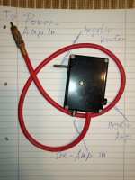
You place a resistor in the minus loud speaker wire to the amp. It´s value should be very low, as it has to take the full power delivered to the speaker.
And send the sampled signal to where/what?
Do you mean the unmodified "Control" signal applied to one voice coil and the "Correction" signal applied to the second? Interesting idea, but I would think this would result in a significant efficiency penalty (with the associated added heat) as the forces and associated currents would be working against each other at times.
Ok, I have no idea about the ratio of levels.
Not sure what you mean. Can you elaborate?
I mean: if R has signal and L does not, L tries to mute R.
But, again, I have no idea of levels.
No, you can not generate a signal from a second voice coil and use it directly to modify the signal. It will not have enough energy ever and interfere with the driving amp.
OK. We need a sensor. I meant a mechanical summation.
You pick up the signal between minus of the speaker and the resistor. Because of the resistor, you don´t have zero volt, but a very small voltage, which contains the amps signal plus the faults generated by the cone. Remember, coil in magnetic field makes voltage.
If you put this signal in the driving amps input and the cone moves as the voltage want´s, nothing is happening. If the cone generates a unwanted movement, the amp will amplify it and correct it.
The only problem is the amount of feed back you apply. Too much and the cone will resonate. So you need a very stable amp and have to take care of DC, as it is amplified too.
With the right adjustment, the cone is really stiff and resits if you push it. The frequency response goes real low and the reproduction is extreme "dry".
OK, this is how I realized some kind of feedback for my sub about 30 years ago. The signal from the active x-over goes to the small box which is plugged into the sub woofer, the feed back is mixed in with the potentiometer and the red line leads to the power amp. I had a 12dB/Oct x-over at 100 Hz.
Please be sure there is no DC to the amp or the input is AC only, which means a capacitor at it´s input. I had a really strong mono amp for each sub, with a 600W toroid.
The difference with and without this little tweak was unbelievable, the bass virtually exploded. Percussion put pressure on your chest, as if you where standing at the stage. Only limit where your ears ringing and the voice coil hitting the pole piece. All from two low budget 12” woofers. As costs are near zero, it is a nice thing to try.
Be careful adjusting when you first connect the circuit, things may go in the wrong direction. A 1A slow blow fuse in the positive lead to the speaker may be a very good idea.
!!!! Warning, only for closed box constructions!!!!!
Attachments
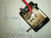
There is a 0.4 Ohm 12 Watt resistor under the PCB. as it was a 8 Ohm woofer, it should be able to handle 240 Watts, which is much more than the woofers rms. The other resistors are 1k Ohm. Today I would make the load resistor smaller in value and the others probably larger, but that is not too critical.
This is sometimes called “negative output impedance”. I did not invent it, as far as I know it was first published by some British DIYS radio magazine, later at the German "Elektor". I have lately seen it being used in commercial sub woofers.
This is sometimes called “negative output impedance”. I did not invent it, as far as I know it was first published by some British DIYS radio magazine, later at the German "Elektor". I have lately seen it being used in commercial sub woofers.
Please take my values only as a starting point and be carefull. I refined them for my last build, so other speakers may respond better with other values.
The basic idea of the publication I had at that time, was to reduce Qtb of a woofer that is build in a much too small enclosure. The article was very brief, from the “Elektor” magazine, that often only published ideas stolen from British or US publications, as I know today. Maybe the translator had not even understood the principle.
I used it with woofers that where housed in acceptable volumes, to extend the low end. To my surprise the precision of the reproduction extremely improved. I heard most of the best and most expensive DIYS speakers at that time, like Focal, Dynaudio, Vifa and Scan Speak, but not one could match this low end reproduction. (I replaced them with a pair of 15” bass bins, but the low end was disappointing)
The woofer I used had medium size magnets, low Fs with medium Qts and high Vas, typical for driver you would use in a large closed box. Maybe a Qtb of 0.7-0.9 in the box, data where not very reliable at that time. Please, what you see on the picture is 30 years old! But I just measured the values with a DMM.
I have found the ACE-bass now, that shows many similarities, with a lot more and active parts. My simple passive version worked perfectly for many years, until the woofers surround fell apart.
Anyway, I also had high and low pass, but indirectly, in the x-over and amps input. I used only a CD player as source, as my record player would resonate with these subs at medium level.
IMO all these solutions are basically the same, only refined and combined with other principles. As long as you only use the resistor in the negative speaker wire, there is only one active component. Sure, you can limit, bend and lift the input signal, but the all important and unique part for woofer control stays the same. I saw one circuit that had a very simple way of inducing some DC to the amps input, so it´s offset could be compensated. Nice idea, but with most amps offset is temperature dependent, so maybe not a solution for all amps.
Today I would put a DSP in front of the woofer, do all the fancy stuff with it and let the feed back only do the correction to lower distortion. Maybe process the FB signal with an op-amp, to make things more predictable.
PS with an op-amp the resistor in the negative line could be much smaller, like 0.1 ohm´s, too.
Last edited:
OK, this is how I realized some kind of feedback for my sub about 30 years ago. The signal from the active x-over goes to the small box which is plugged into the sub woofer, the feed back is mixed in with the potentiometer and the red line leads to the power amp. I had a 12dB/Oct x-over at 100 Hz.
Please be sure there is no DC to the amp or the input is AC only, which means a capacitor at it´s input. I had a really strong mono amp for each sub, with a 600W toroid.
The difference with and without this little tweak was unbelievable, the bass virtually exploded. Percussion put pressure on your chest, as if you where standing at the stage. Only limit where your ears ringing and the voice coil hitting the pole piece. All from two low budget 12” woofers. As costs are near zero, it is a nice thing to try.
Be careful adjusting when you first connect the circuit, things may go in the wrong direction. A 1A slow blow fuse in the positive lead to the speaker may be a very good idea.
!!!! Warning, only for closed box constructions!!!!!
This is a form of current drive.
For the German DIYS community --- The reason why is quite simple. --- dealership a way out -- components for passive crossovers have skyrocketed to ridiculous high´s.-- Mr. Mundorf and his friends will not sell there 1000 times overpriced nonsense parts -- The smaller loudspeaker for more money may sound better, the uninformed consumer puts weight and size on the scale and makes her/his decisions where she/he gets more. -- DSP and amp chips get cheaper by the hour -- PA : cone area
I feel the same more or less applies to the Dutch DIY community with an increasing market share for exotic caps & coils, quantum improved fuses, esoteric cables and groovy ground boxes.
All it takes for us is to proof real gains are not with those but with energy being converted from electrical to mechanical and that by controlling this conversion with feedback improvements are possible which completely outrun any audiophile trickery by a thousandfold.
MFB was hard to implement back in the 70ties due to the obligatory amplification & filters that all happened through hole and thus labour intensive & expensive. Nowadays like you said it's SMD & class D, just imagine what would happen if finished aliexpress modules would drop below 10 euro. You don't need a large company any more to have your gear build in Malaysia, just post the designs here, make a lot of noise and wait for some Chinese friend to turn up.
On a last note, music just wasn't ready for mfb back in the 70ties. Vinyl based low frequency signal transfer suffered from hop, skip and jump when LF wasn't cut mono hence the infamous 2:1 selling point "there is no stereo information below 50hz". Compare that to say modern day Skrillex.
With regards to MFB and PA, just daisychain and prepare to be AMAZED

Last edited:
Hi,
Thanks for the link to Chris Camphuisen whom I did not know, but he seems quite dedicated to the idea. As far as I can see from the pictures he also uses piezo discs to measure the acceleration. However, if I were to experiment with it now, I would try a more modern device - for example the ADXL337 or similar.
As for the "one amp" idea - I'll scan the article and (if copyright permits!) post it here some time.
Main problem with these special acc. chips : noise! The main enemy in MFB is noise generated by the sensor.
Last edited:
Main problem with these special acc. chips : noise! The main enemy in MFB is noise generated by the sensor.
I think you are right that this is an issue. Either a lower noise floor or a higher signal is helpful. Chris has been working through this from a practical point-of-view and his accelerometer assemblies seem to have evolved accordingly.
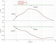
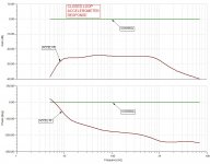
I was sidetracked a bit but now I'm looking at the circuit analysis again. Things weren't working as expected and I discovered a problem where the signal out of the Accelerometer Interface was low and clipped. I was feeding an op amp signal directly into it so perhaps it is one of these impedance mismatch issues or similar that mechanical guys like me don't understand.
In any case, I bypassed the Accelerometer Interface and obtained the following plots without and with about 15 dB of feedback.
In any case, I bypassed the Accelerometer Interface and obtained the following plots without and with about 15 dB of feedback.
Attachments
For practical use I would like to point at two problems with the amplifier used:
The amp shall not invert the signal and you can not use bridged amps in this passive configuration. If the amp does not meet this specification you have to use some active stage to process the signal. Solution would be to invert or float the signal. There is a description in the forum somewhere how to do it.
I used a 1A fuse in the positive lead for my first experiments, which later was removed. Somewhere I read about using 12 Volt car lamps to limit the current, if something goes wrong they heat up and the resistance gets higher.
Two things can "go wrong". The woofer can start to resonate like mad or, if the feedback is to much, the cone can be driven in one direction from DC. With my amps the right amount of feed back was reached when the cone moved out of the zero position about half a millimeter. More and it would suddenly move all out. This was IMO no problem, as there is no limit in the "cone out" direction. If it moves in, you loose distance to the pole piece and can damage the voice coil. Take care. I´m sorry, this is 30 years old experience!
Once I got all the components right, it was a really simple modification, done in a few hours.
I tried smaller woofers two, this was impressive, but for my ideas about bass reproduction not sufficient.
What ever you do with loudspeakers, cone area and cone excursion are mechanical limits you can not overrule. All these “small woofer-impressive bass” constructions come at the price of high excursion and high power to move the cone in and out. The “wow” effect often is not quality reproduction.
IMO if you use a large woofer in a not to small enclosure, you go the HIFI way, as you really improve the sound over the unregulated speaker. Don´t make a bad construction acceptable, but a good one better.
@ds23man
This is a form of current drive.
Hi, I´m sure you are right about current drive. I appreciate to be corrected, as i´m only a hobbyist.
But, if you have only the voltage from the negative lead as correcting signal, all these interesting and patented ways of improving the response of loudspeakers are just what?
You can not take an elephant, put him in leisure wear and call him a vacationer, he will always be an elephant, right?
The only “feed back” comes from the voice coil/ series resistor, the other measures are called feed forward, as far as I know, as they do not react to anything the cone/ voice coil will do.
Maybe we should first see what the basic current drive really does in a construction, then add the rest and look at it again.
IMO the real improvement on distortion and resulting better sound comes from the correction signal. This is what makes the driver perform better.
Might be interesting what is left if you take away the woofers signal from all this?
The “current drive” is the main advantage and the main problem, because you can not put a circuit just in front of the loudspeaker, but you have to integrate and adjust it. Which makes things very complicated, as drivers have absolute tolerances and change their parameters while in use. So no good for cheap mass production and only usable with active driven subs and speakers.
In the end the resistor is not the best way at all. Any real signal sensor should do better, I think about glueing a microphone to the cone for correction, not more expensive in the DIYS world.
Turbowatch2 - I think your idea is what is also called application of "negativ impedance" (and I suspect that is another name for current drive???) There is a full investgation of this issue in an old article from The Audio Engineering Society called "Application of Negative Impedance Amplifiers to Loudspeaker Systems" - the article can be purchased here: AES E-Library >> Application of Negative Impedance Amplifiers to Loudspeaker Systems. Your application is much simpler but I have no doubt that is works very well. It is interesting that, according to this article, the "negativ impedance" approach reduces distortion with the same amount as acceleration feedback with e.g. a piezo disc as well as it widens the bandwith downward.
Some years ago a British audio/electronics magazine had a similar project.
Some years ago a British audio/electronics magazine had a similar project.
- Home
- Loudspeakers
- Subwoofers
- Motional Feedback Speaker Project - Circa 1981