Hey everyone. I'm involved in a project where I need a 30Hz Square wave reproduced above 90db If using a speaker, I can't have any box or enclosure behind the speaker and I need it as small as possible. Anyone know where to start looking?
Thanks.
This is NOT for music so sound quality doesn't matter as long as the Hz and db requirements are met.
Thanks.
This is NOT for music so sound quality doesn't matter as long as the Hz and db requirements are met.
To accurately reproduce a 30 Hz square wave would require a driver with no mass, so start looking for nothing ;^).
Previous discussions here:
Can't Reproduce a Square Wave.
If sound quality, that is, accurate reproduction, does not matter, there are many sub woofer designs capable of 30 Hz 90 dB at one meter, you will have to be more specific in what your definition of "small" is, and what you mean by "I can't have any box or enclosure behind the speaker".
I need a 30Hz Square wave reproduced above 90db If using a speaker, I can't have
any box or enclosure behind the speaker and I need it as small as possible. .
There's no chance of a 30Hz square wave, you'd need flat response down to around 5Hz.
Maybe a 30Hz sine wave at high distortion. What is this for?
Last edited:
30Hz Square
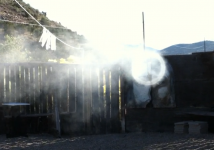
Currently we use a Function Generator sending a 30Hz Sq. Wave to a 1000w Amp then to a 10in Sub. The sub is not in an enclosure but does have a waveguide, (Nothing Behind it) and we want to find a speaker/driver (are these 2 terms interchangeable?) that can produce the same result but is smaller than 8in if possible. Not being big acoustic people we are not sure how small we can go to reproduce the wave. Life of the emitter is not important as long as we can get a few hours out of it. 1Kw is our maximum power we can send to the speaker. The application can be seen at forcesv.com, as well as visual examples of our current setup.
Currently we use a Function Generator sending a 30Hz Sq. Wave to a 1000w Amp then to a 10in Sub. The sub is not in an enclosure but does have a waveguide, (Nothing Behind it) and we want to find a speaker/driver (are these 2 terms interchangeable?) that can produce the same result but is smaller than 8in if possible. Not being big acoustic people we are not sure how small we can go to reproduce the wave. Life of the emitter is not important as long as we can get a few hours out of it. 1Kw is our maximum power we can send to the speaker. The application can be seen at forcesv.com, as well as visual examples of our current setup.
This is NOT for music so sound quality doesn't matter as long as the Hz and db requirements are met.
Is it for human hearing or for some mechanical purpose? Airborne or mechanical? Clean?
What are you doing?
B.
1)Your "waveguide" is rather more a vortex cannon. Speaker/driver/transducer are generally interchangeable terms. Your vortex generator relies on large and rapid air displacement. Reducing driver size (Sd) requires an increased linear travel to achieve the same displacement, which is measured in Xmax, one way travel. The drivers depicted on your website do not have particularly large Xmax, and use ceramic magnets- neodymium magnet structures would greatly cut the weight to strength ratio, but increase cost.1)The sub is not in an enclosure but does have a waveguide, (Nothing Behind it) and we want to find a speaker/driver (are these 2 terms interchangeable?) that can produce the same result but is smaller than 8in if possible.
2)Not being big acoustic people we are not sure how small we can go to reproduce the wave.
3)Life of the emitter is not important as long as we can get a few hours out of it. 1Kw is our maximum power we can send to the speaker. The application can be seen at forcesv.com, as well as visual examples of our current setup.
2)Unlike a loudspeaker, which is designed to reproduce a wide range of frequencies, your vortex generator appears to be producing a pulsed toroid of air. The pulse frequency may be 30 Hz, but the acoustical output at that frequency is not really applicable, the 30 Hz acoustical output is omnidirectional from the "waveguide" (cannon). The rotating taurus of air emmited is what is doing the "work" of maintaining directionality at a distance usable for "blowing out" fire.
To reduce device size, and increase stroke, a solenoid could directly drive a piston in the cylinder. A Geneva drive using rotary motors could also be used to drive a piston in a more "square wave" fashion.
3)1000 watts is going to limit your device to "toy" status, to be of useful fire-fighting use will require much more power to drive much larger air pulses further distances. Lightweight motors with 5-10 peak horsepower (4-10kW) are far less costly than pursuing standard acoustical transducers to achieve your desired effect- a directional pulsed air train.
I'd suggest filling your device with smoke from a fog machine, video tape the torroidal output, and view the results in slow motion to see what is actually making your device work ;^).
Cheers,
Art
Attachments
Last edited:
Need to start checking if anybody has replied before hitting the post button, ho hum. If pulses are what your after then possibly a 4th order bandpass tuned tube may work, tune for a very high gain at 30Hz and size the port so as to produce high velocity pulses, something like the motor system and dome from a Precision devices 24"?
There is an attraction park of science (Palace of Wonders), where there is a sound cannon on show. It consists of a tube about 3 feet diameter, 6 feet long. The rear end has a rubber diaphragm, activated as one-shot. The other end has an opening of about 1 foot, where the sound pulse is propagated out. The target is at a distance of about 25 feet, and the sound pulse travels quite coherently, with very minimal dispersion.
I suppose a large energy sound pulse is easier to generate mechanically on similar principle, than by electroacoustical transducers. And for your purpose it does not need to be a square wave, it can be a step pulse (that is the leading edge of a square wave) like in the above example.
The issue with a loudspeaker at low frequency is (beside the difficulty at reaching low frequency at reasonable acoustical power), that they are omnidirectional. I believe you can find more info on the the sound cannon device on the web.
It is not a "sound pulse", it is the torroidal vortex air pulse ring that travels coherently. The torroidal spin tripped by the large volume of air through a reduced diameter exit stabilizes the ring as it travels forward, according to the Bernoulli Principle.The target is at a distance of about 25 feet, and the sound pulse travels quite coherently, with very minimal dispersion.
In the OP's fire suppression device, the objective is the stream of torroidal air pulses, any sound generated by it is just another form of wasted energy.
Last edited:
I don't think getting a pretty decent 30Hz square wave out of a speaker would be all that hard...with some major caveats....
First, it has to be a full range speaker.
No sub can do it, since square waves are the fundamental plus odd harmonics out past audibility.
Second, the full range speaker will need to have been tuned to ruler flat mag and phase (anechoic)
Third, no reflections to muck things up.
Last, you'll get a super looking 30Hz square wave at only one spot...the tuning spot.
IMO, the real test of a truly great speaker is how well square waves hold up off axis.......
Googled Vortex Cannon.
No need for square wave I think, only rapid push of air by a cylinder and then retract. Long throw speaker driver with power full motor? Invent and build small Pulse Detonation Engine")
Wen't to loudspeakerdatabase.com. Most powerfull 8" driver I found was some Skar audio sub with BL of ~20, Skar Audio ZVX-8 - 8" Subwoofer. Here is a 6,5" driver DB Drive WDX6.5G2-4 - 6.5" Subwoofer
No need for square wave I think, only rapid push of air by a cylinder and then retract. Long throw speaker driver with power full motor? Invent and build small Pulse Detonation Engine
Wen't to loudspeakerdatabase.com. Most powerfull 8" driver I found was some Skar audio sub with BL of ~20, Skar Audio ZVX-8 - 8" Subwoofer. Here is a 6,5" driver DB Drive WDX6.5G2-4 - 6.5" Subwoofer
Last edited:
I apologies to disagree from the mates.
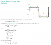
Theoretically, it's possible to reproduce square wave because as demonstrate by Fourrier theorem, the square wave is a summation of many sine waves, and sine waves can be perfectly reproduced by real world speakers.
Probably to reach as much close as possible to square wave, you will need not only one speaker but some of them and due to comber filter you might get square wave just in a very specific space, you also might need individual delay and individual amplitude control for each speaker. The speakers amount you might need depend of the amount of sine waves you need to sum to reach to your square wave target.
Fourier Series--Square Wave -- from Wolfram MathWorld
There are other links with more in deep information. The theorem is easily simulated using Matlab software.
Attachments
Last edited:
...Theoretically, it's possible to reproduce square wave because as demonstrate by Fourrier theorem, the square wave is a summation of many sine waves, and sine waves can be perfectly reproduced by real world speakers....
Have you given any thought to phase? Have you thought about a mic sitting at a non-trivial distance from a speaker (which itself is a non-trivial extension in space, as is always the case in the real world)?
As soon as even a very little bit of phase shift between different frequencies occurs, the image in the oscilloscope is totally shot to hell.*
All the frequencies are still there - just like in the Acoustics 101 diagram you posted. And this may result in no effect on how the square wave sounds.
B.
*the mic in the test set-up can further destroy the oscilloscope squareness for the same phase reason
When i suggest delay I was thinking about phase, did you thought different?
He is not worrying about how square waves will sound, so, nether we should.
The magic happens when someone can bring to real life what is first discovered by theory.
You don't need to argue against me, Fourrier theorem is know by many year and it was already proved. It's just about time and effort to make it work for a specific case and place.
When i suggest delay I was thinking about phase, did you thought different?
He is not worrying about how square waves will sound, so, nether we should.
I'm having a lot of trouble making sense of your posts.
You seem to arguing from both sides and all sides at different times. Sometimes being very anchored to physics and sometimes being very mystical.
In what seems an obvious reference to the oscilloscope visual appearance of a mic pick-up, you say, "to reach as much close as possible to square wave". Right? Other times you say you only care about the sound. Or in the above quote, like you don't care what it sounds like. Right?
BTW, I said the square wave might sound just fine but unlikely to look good on a scope (except on a lucky night). You did notice that?
B.
Try to read the post from macro point of view to a micro one.
When talking about theorem we are talking about general rules.
"A theorem is a proven mathematical statement. To prove a statement means to derive it from axioms and other theorems by means of logic rules, like modus ponens. A proof is needed to establish a mathematical statement."
Do you know what is the Fourrier theorem and how the math works? Basically it says that any signal can divided by a series of sine waves. Once it's a general rule, it could be applied to many things like: Ocean waves, electrical waves, sound waves, etc
Finally, when talking about sound square wave, as I said, in theory it can be created by a summation of many sine waves, more sine wave is added to the signal, more sharp the square wave will be.
See the video below with a good animation, it may help to clarify.
YouTube
Note.: The image is a simple graphic, not an oscilloscope.
- Status
- This old topic is closed. If you want to reopen this topic, contact a moderator using the "Report Post" button.
- Home
- Loudspeakers
- Subwoofers
- ISO 30Hz Square wave reproduction.