hmmm.
I need to look up the build thread. This makes me want to take the actual dimentions of the horn and provide them for you to check. at the time it was bassed on a horn build that was symaltanious but with a 30 hz tunning. I lengthened the path. the sub is 2m20cm tall. to me I have always been exeedingly pleased with its performance and im sure it isnt tunned to 20 hz beause I did freqancy tests at at 20hz the driver is unloaded
Thanks btw.
Found the Thread, Just looking for the Relevent Information. It was the same as the 30hz one mikehunt built but I basically streched it as I opted for a lower tunning.
Collaborative Tapped horn project
My user name was Naudio at that time.
Collaborative Tapped horn project
My user name was Naudio at that time.
Last edited:
Hi
Quote: 'was my sim actually correct?'
Answer= No
b")
Should also be set to 2*PI not 0.5*PI, unless you're trying to determine what the response would be like when located in a corner...
Corner horn...?
Hi,
you said you want:
Bass! down to 30 Hz.
Size is not a problem.
Instead of using the woofers you have which are semi suitable, why not build a corner horn with a 18 inch woofer?
The corner horn works well with cheap and weak magnet PA chassis. Damping is done by the compression chamber, a strong magnet would just work against it.
Search for Niwo Eckhorn for example. The initial of Wolfgang Nickl who build a 18 inch corner horn. This is working as horn down to 30. And it triggers the next seismic sensors..if you push it. But can be very delicate, too. Also very dry and neutral. Not like many ported designs with an annoying boom effect.
I use it up to 100Hz. 'Normal' speakers are Mickey Mouse to me since I am using it.
Using your woofers from 100Hz might be a better use for them. Less stress.
Best
Thomas
This is the most relevent page of information on the topic I can find. as I dont have my origional sims and they are no longer hosted as I didnt know how to upload them directly into the forum.
Collaborative Tapped horn project
I sence I had some level of confusion at the time.
The sim, I sent bjorno the picture of is included there,
I was Confident that My Actual design was my destined 25-75hz and as I recall it was rather much like taking mike hunts horn and elongating it to add 80cm(approx) to the path length.
Real want to figure this out. I have been happely using this for 10 years!
The next thing to do would be to actually Mesure the horn itself s best I can when I next relocate it.
I am hoping Bjorno can with his, knowhow of such, decipher that information rapidly enougth to see what I actually built, Hopefully had the responce that I opted for and is Good in the rhelm of basshorns.
Hi
Quote: 'was my sim actually correct?'
Answer= No
b
 Hi, What I am Bassicaly needing to decern is was it That simulation that was Incorrect
 or is that simulation showing what I actually Did build!
If I simulated the dimentions Correctly, as the 'elongated' mikehunt horn. would it arrive at the responce I had simulated.
I knotice the names for values differed, is this the type of expantion?
was it something to do with the horn flare? I know I very much have built a horn of Likely not thaat many liters! but at the time I did relate the information between the hornresp and the plan.
sorry tired writing, I need to sleep on this.
also the speaker parimiters used differ from te ones TB46 used back in the day, does that mean his where incorrect?
also in his added pdf file, he says system volume is 194Liters
some missmatch of information
this is the page with the most of it, including a pdf, but when I made the hole for the driver I most certainly made it the same size as the drivers radiating area, it looks about right proportionatly. The Pdf. ....I wonder how that differs from his sim he provided. or how mikehunts horn simulates. or a NEW simulation showing mike hunts horn with added 80cm (ish) path length. as that was bassically all I did. would be Grand indeed to find I did actually get a horn that was the 25-75.
Collaborative Tapped horn project
I have , somewhere backed up saved information from these days, I will see if I can dig out my atual Plans and simulations. I would very much like to find out that was the sim and not my horn! phew
Hi All,
FYI: Another Picture showing x-max and Sd Calculation
b
Cool! Thanks! I got Sd 'close enough', but didn't know the math to even begin to check Xmax, just convinced the surround wasn't nearly large enough to handle it based on some high excursion PRs I have stored away, but chose to ignore it anyway for the time being to sim a 'what if' TH.
GM
Hi
Bjorno,
Could you run a re sim bassed on the size and dimentions in the PDF. in the thread I linked to.
as far as I know, (as I cannot locate my origional plan and simulations) this is the dimentions I used. very close anyway. I need to check it was that sim that ws incorrect and not the actual Speaker!
I do recall I made the exit slightly larger,
and one minor note, I used the full surface size of the driver radiating into the throat of the horn.
I am happy to provide a re mesure of the cabinet so I an provide the exact dimentions of the horn. I hope that if the Horn is Modeled correctly in hor responce it will show the Tuning I opted for ad as far as I know Have.
Thankyou,
Hi
Bjorno,
Could you provide me with a re-sim bassed on the dimentions shown in the Pdf on the page I linked to?
Collaborative Tapped horn project
As far as I can recall this was the dimentions I built, very close. I know I made the mouth slightly larger, square infact.
It was the same as mikehunts horn, (also in the thread) but the final hight was 2220 tall. I bassicaly streched the design to opt for a lower tuning than his. this added to the path 81.22cm, and made the mouth square. I wonder how His would model? if it would show as true, but more importantly I want to ensure the horn I built actually has the passband I opted for. I saw it to be 25-75 cycles.
I would like to see if the simulation I sent you was incorrect. If you can provide a resimulation bassed on the actual dimentions of the speaker I Built, I will be most greatfull,
Thankyou,
Nathan.
Hi, Here is the Pdf.
That and the imformation is on the page I liked to?
earlyer in the thread should be mikehunts words and also his build dimentions, I simply used those, and made the horn longer and enlarged the mouth a fraction.
It simulated well.
The pfb supplyed is by the same person who did the simulation I posted that Bjorno re ran, showing a very different responce. If there where a way to compare the sim of TB46 with the PDF of dimentions and see where the error lyes. See if the dimentions equate to Bjorno's re sim.
sadly All the images showing my own imput data are not in the thread as I didnt upload them directly. and I dont have the information on my current computers.
The best I feel I could do Is to make some accurate mesurements, or to look at mikehunts horn and imput data and add the same size expantion and hope it simulates to.. 25-75cycles
Thankyou,
Collaborative Tapped horn project 2
also relevent Collaborative Tapped horn project 1
I have not mesured the responce with a microphone.
Attachments
Last edited:
This! I recognise.
It is bassically this, but 2220 long/high, the dimentions at the turn around where kept the same, so the inner path section was a corresponding angle to the slightly lengthened cabinet.
I made the mouth area Square.
GM: This is Your simulation I found for William Cowans 30hz Tapped horn That MikeHunt used with the Eminence Magnum Pro 12HO
and a Link to this Page.
Collaborative Tapped horn project
I bassically used the same enclosure, with some length added.. (81.22cm)
So the final Horn was 2220Tall with a very slightly larger port. I used the eminence definimax 12
so we have the Cabinet, and we Have .. what I hope is True input data.
Simply this. but longer/lower tuned. Should model and be as 25hz-75hz?
I Sure hope what I actually built Is 25-75hz
Attachments
Those earlier attempts at Hornresp TH sims tend to be a bit off.
Typically:
1. Segments are sim'd as conical (CON). They should be sim'd as parabolic (PAR) if the horn is being folded up into a rectangular box with at least one dimension remaining constant (like your example).
2. No "cone compensation". Vtc and Atc should be used to sim the volume of air between the cone and the start of the TH.
3. Incorrect path length calculation. The "advanced centerline" path length calculation approach usually gives the closest results when comparing sims to actual measurements of the built systems. I use the advanced centerline approach for my horn design spreadsheets - The Subwoofer DIY Page - Horn Folding
And more recently, the "Lossy Le" or "Semi-Inductance" options should be used if the drivers are long-excursion drivers. In fact, I suggest using the "semi-inductance" option wherever possible, though you will need to obtain the required extra driver parameters first in order to use it.
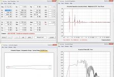
The bad news is that Hornresp sim you posted is way off.
The good news is that a corrected sim does look you might have hit your target, if the dimensions of your TH are a close match to those given in the spreadsheet.
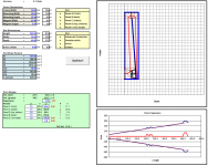
Attached are:
1. An optimized sim of a single-fold TH using the external dimensions you provided, and the location of the internal panel at S1.
2. An adjusted Hornresp sim, based on (1) and the actual dimensions of the mouth of your TH. The difference between 1 and 2 is minor.
I'll be making the optimization spreadsheet available from my site once I've finished work on it.
The good news is that a corrected sim does look you might have hit your target, if the dimensions of your TH are a close match to those given in the spreadsheet.
Attached are:
1. An optimized sim of a single-fold TH using the external dimensions you provided, and the location of the internal panel at S1.
2. An adjusted Hornresp sim, based on (1) and the actual dimensions of the mouth of your TH. The difference between 1 and 2 is minor.
I'll be making the optimization spreadsheet available from my site once I've finished work on it.
Attachments
Wow thats looking Good.
The box is looking to be the right shape too, One thing this shows so far is the Tunning of the box Is likely as Intended, so umung that muddle of simulations I may have somehow Got it as I intended/ment,
would be curious to see if the 30hz tuning also parralels, could be a great little horn
The resim with the eminence will be greatly appreciated.
The specs you used look simuler to the definimax, BL is one that corresponds closely. That itself is good sign.
Im trying a simulation now, though unsure What driver perimiters to trust. Then I will endevor to Mesure the Actuall horn accuratly tomorrow and provide my exact dimentions They should be right as you have them, but to be sure its pitch perfect. Panel thickness 18mm. I Did add a small amout of bracing, angled mdf 'wings' along the length, 5 of them each side of the expantion. slanted to fit, each about 4 incheslong 18mm wide. This would effect very margionally. but would have decreased the volume veery slightly.
I can, from my time using my sub, say I love it yes. so for what its worth I would recommend it to others, However I am not sure how good it is, when compared with the many other designs out there. first to assern its frequany responce and things are in check.
Last edited:
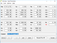
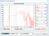
Hi, This is my attempt of simulation, combining,
Bjorno : The Eminence definimax12ho driver perimiters
Brian Steele : The hornresp input data
I did change 2.0 to 1.0 as a personal preferance, as Thus far where ever I have placed the horn it has been closeish to one corner but not in, out abit along a wall.
I would Like to Mesure this horn, give back to the community,
For me the speculation is with the driver Parimiters, and Im to tired to google how to spell that word right now.
Its not yet showing the ruler flat responce of before times, it Is however markedly improved.
ps: I did employ slight dampening, a fleace blanket hung in the mouth from one of the braces..
Attachments
Last edited:
- Status
- This old topic is closed. If you want to reopen this topic, contact a moderator using the "Report Post" button.
- Home
- Loudspeakers
- Subwoofers
- Tapped Horn "experts" wanted