Hello, first post here in the Subwoofer dep't.
I have had 2 of these sub's working for about a year using SB Acoustics SB23MFCL-4. I was running them all in parallel for a 1 ohm load, torturing my poor Audiosource Amp3. In fact I did finalyl destroy one of these fine Amps after cranking it up without a warm-up period...
Well now they're being individually powered by IRS2092S 380W class D amps each. 2 separate 500W SMPS's powers a pair of these IRS2092S amps. miniDIGI+miniDSP are on the front end for EQ and SPDIF optical is used. Warning: These China amps needed a mod to work properly...
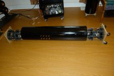
I've found it runs best when the 2 top drivers are run inverted from the bottom 2. The top and bottom drivers are spaced about 1/2" away from the end of the tubes, so it can be considered a vented system. Inside the tubes the drivers are very tight. With 12AWG wiring to the input connectors going around the drivers, the PVC tube slides very tightly over the bottom 2 drivers. Same when mounting the top to drivers... The PVC tube is 5/8" thick and 4ft tall and about 8.82" ID, so about 2.2cuft.
My question is how to find out the the F3 and SPL on this setup? Thanks!
I have had 2 of these sub's working for about a year using SB Acoustics SB23MFCL-4. I was running them all in parallel for a 1 ohm load, torturing my poor Audiosource Amp3. In fact I did finalyl destroy one of these fine Amps after cranking it up without a warm-up period...
Well now they're being individually powered by IRS2092S 380W class D amps each. 2 separate 500W SMPS's powers a pair of these IRS2092S amps. miniDIGI+miniDSP are on the front end for EQ and SPDIF optical is used. Warning: These China amps needed a mod to work properly...
I've found it runs best when the 2 top drivers are run inverted from the bottom 2. The top and bottom drivers are spaced about 1/2" away from the end of the tubes, so it can be considered a vented system. Inside the tubes the drivers are very tight. With 12AWG wiring to the input connectors going around the drivers, the PVC tube slides very tightly over the bottom 2 drivers. Same when mounting the top to drivers... The PVC tube is 5/8" thick and 4ft tall and about 8.82" ID, so about 2.2cuft.
My question is how to find out the the F3 and SPL on this setup? Thanks!
Attachments
Last edited:
Am I missing something? I've never seen anything like this before. It seems to me, if the inner drivers seal against the walls of the tube, that you have a sealed alignment for those two, although it probably leaks enough that it isn't technically sealed. The outer drivers, if they are spaced away from the tube end, are operating open baffle, which at 90 degrees off axis will mean that they provide essentially no output with the back wave out of phase with the front. I would guess that it would operate better without the two outer woofers connected at all and with just one woofer per end perfectly sealed and mounted flush. Of course first the driver parameters would have to be known and modeled to find out if the enclosure volume is appropriate. Perhaps I am not understanding the picture and description correctly. Can you explain why you did not use a conventional alignment and what you thought the benefits of this alignment would be? Btw, I love oddball experiments, it's just that they very seldom work out. ") . Craig
. Craig
. CraigI guess I never answered your question though. F3 and spl is determined a couple of ways. Use a signal generator app on your phone or laptop to feed varying frequencies to the amp inputs, then use an spl meter and measure. Or alternatively and vastly better, get a measurement microphone and REW. I like the UMIK. To eliminate the room effects measuring outdoors away from any structures is best, but in room can be okay for your purposes often.
Hey Craig and thanks for your thoughts!
The initial/simpler idea comes from an isobaric design where 2 identical drivers are in phase in a sealed enclosure. The idea was to use 1/2 volume to achieve the same F3 when compared to using a single driver... I realize nowadays, subwoofer drivers have come a long way and don't need as much volume as I have here, especially considering the # of drivers.
I might agree with you that 2 drivers may achieve the same result here, i.e. 1 on each side of the tube. I can come close to simulating this by muting either the inner or outer drivers, which could simulate sealed vs. unsealed with the unused driver acting as a passive radiator? But I think under high SPL the drivers will help each other out if they're all powered.
I'll post an updated pic late. Thanks!
Is there really a space between the tube and the outer driver? Because that changes everything. Any air leakage anywhere changes things entirely.
The inner drivers have a gap of about 2mm equal from the ID of the PVC tube.
The outer drivers do have a 1/2" gap due to the way I currently have them mounted...
Measure what you have, then convert it to a well sealed design with one driver on each end with zero air leakage, then remeasure and listen. You will find it capable of much higher output and lower F3. What you have now is impossible to model and very unlikely to give good results. I think it's awesome that you just built it! But some modeling will give better results 99.999% of the time. Do have the TS parameters for the drivers? Get winisd and start playing around. Good luck! Craig
Measure what you have, then convert it to a well sealed design with one driver on each end with zero air leakage, then remeasure and listen. You will find it capable of much higher output and lower F3. What you have now is impossible to model and very unlikely to give good results. I think it's awesome that you just built it! But some modeling will give better results 99.999% of the time. Do have the TS parameters for the drivers? Get winisd and start playing around. Good luck! Craig
Thanks, I'll take that advice. I actually built them earlier this year. They have been in service for about 6 months. I'm very pleased with them, even more so now that they are individually amplified and EQ'd. The other day I was watching the movie Unbreakable in the background while working on the laptop. I heard nothing unusual but felt the laptop rattling underneath my hands. The 1 sub was about 10ft away against the wall far from a corner.
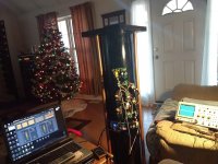
Here's a more current pic. It's more solid with a wider platform made from 2 layers of birch plywood glued together and 3 stabilizer bars, which are repurposed mop handles painted copper.
This is when I installed the MiniDSP Advanced 2x4 plug-in and was using a Plenue 1 audio player for the SPDIF digital source. Thins were not working initially which is why the 'scope is there...
Attachments
Last week I did some testing with REW and the Dayton mic placed in the center of the living room. The sub was about 5 ft away from the mic and any wall. Close to me so I could program the DSP. There was a dip from 40Hz-60Hz and a nasty peak at around 200Hz. And this was with a 48dB 150Hz LP filter on all 4. So I used the parametric EQ's to flatten it all out and it was good. This was with the sin sweeps from 10Hz-200Hz.
Next test was pink noise starting at low volume. Audio is coming from a computer SPDIF out straight to the miniDIGI/miniDSP boards then RCA out to the IRS2092S's. Slowly raising the volume, one of the amps gave out. Fans stopped blowing and no output. Thank God it didn't slam the output to one of the +_65V rails. It went quietly. Replaced the amp, after another one blew in the same position I am starting to suspect the errant SMPS that outputting +74V-60V but the other amp it is driving never blew out. Maybe coincidental? Replaced that amp, and did more stringent testing with no more blowouts. Was seeing output voltages of +-30V on the sin wave testing and close to +-20V on the pink noise tests. More testing today, with pics.
Today I will replace a resistor to increase the gain from around 40 to 46 in order to deal with the measly .9mV output from the DSP in order to try to maximize the outputs of these amps.
Careful not to blow them trying to get a max spl in the current box setup. Very likely as soon as hear them in a properly sealed enclosure you won't look back.
You're probably right. I need to take reasonably exacting measurements, SPL meter, 'scope measuring amp output voltage, REW w/cal'd mic. Next monday testing will be in session...
The inner drivers have a gap of about 2mm equal from the ID of the PVC tube.
The outer drivers do have a 1/2" gap due to the way I currently have them mounted...
FYI. No seal anywhere. They are essentially 4 drivers operating in free space. With 2 out of phase with the other two. (he's operating the outer drivers in reverse polarity). I'm curious to see if the measurements are surprising. Always good to experiment, it's a very unusual setup. One would assume that the excursion would limit the output severely. Coupled with the cancelation from the reverse wired drivers...... The only unknown is what does an unsealed tube around the drivers do? If it does anything, it would only be at high excursion when there is significant resistance to air travel in that 2mm gap. It's an odd setup but once in awhile these experiments will teach us something, keep it up!
One correction: the 2 drivers on top are out of phase compared to the 2 on the bottom. Since I can do this very easily and quickly using DSP I tried all combo's. This current setup, I just explained, seriously increases the SPL compared to any other phase combo.FYI. No seal anywhere. They are essentially 4 drivers operating in free space. With 2 out of phase with the other two. (he's operating the outer drivers in reverse polarity)...
Ahh, thanks for clarifying. It's strange that it would increase spl. At bass frequencies, with such long wavelengths, it should only increase output around the wavelength equal to twice the length of the tube (where the out of phase signals will be in phase again). Of course that's assuming drivers where the back wave is controlled in some way. In your set up, it shouldn't matter anyway because the back of the cone is another speaker radiating out of phase with the front. And the sound of the back of the cone is leaking out, meaning essentially you have 8 drivers total, with half of them out of phase with the other half, regardless of how you do the polarity. But there's still the unknown of the unsealed tube. Hope that makes sense. We'll see what the measurements look like compared to sealed.
That makes sense actually. I think I know why now. With the top two drivers facing the opposite direction, wiring them in reverse polarity means they are pushing the enclosure in the same direction. You've made a tactile transducer for your floor!unfortunately, this is the opposite of what you generally want to do with a subwoofer. You want to hear the sound from the driver, not from the floor.
- Status
- This old topic is closed. If you want to reopen this topic, contact a moderator using the "Report Post" button.
- Home
- Loudspeakers
- Subwoofers
- 4x 8" Subwoofer experiment.