1:1 CR, like is required with vintage spec drivers with huge Vas, low Xmax/Mms, Fs. Modern drivers can handle at least 2:1 and most at least 2.5:1 and if it's rated a horn driver with low Xmax, moderate power handling used in a domestic HIFI/HT app, up to 10:1 has been known to work in FLH, but doubt it would in a TH unless it has a REALLY low Vas.
GM
GM
This I didn't know, though after checking various 'oddball' sims where S2 doesn't work, Sd does, so maybe add it to the HELP file and delete the S2 option?
Hi GM,
S2 applies to TH and OD horns. It becomes S3 for an OD1 horn, and S1 for other types. It depends upon the location of the driver.
There is a generic statement in the Help file regarding context-sensitive messages. Compression ratio is not mentioned specifically because different information is provided depending upon the parameter selected.
Kind regards,
David
Attachments
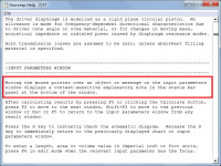
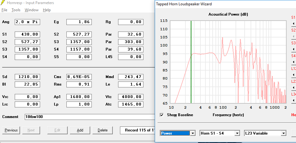
About the CR discussion, i understand the 3:1 ratio as general rule to make a design, but in my opinion is not a valid point to discard a design only because the ratio is bigger than 3:1, for example this the diaphragm sound pressure at xmax, 14mm, in my design that have a 4.14:1 CR.
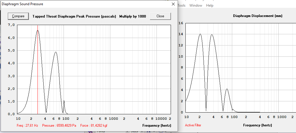
A max force of 82kgf, and now lets imagine that the driver is not 14mm xmax, it´s 8mm xmax, and the diaphragm sound pressure now looks like this

Now the max force is 46kgf, the force that the cone suffer is not only dependant of the CR, it depends too in the xmax of the driver, and in HR is very easy to see the force applied to the cone, and because of this i think that is better to say "not go more than X kgf", the X value will be diferent for each driver, but what will be a good general value to X?
A max force of 82kgf, and now lets imagine that the driver is not 14mm xmax, it´s 8mm xmax, and the diaphragm sound pressure now looks like this
Now the max force is 46kgf, the force that the cone suffer is not only dependant of the CR, it depends too in the xmax of the driver, and in HR is very easy to see the force applied to the cone, and because of this i think that is better to say "not go more than X kgf", the X value will be diferent for each driver, but what will be a good general value to X?
Attachments

This part is incomplete, because the kgf figure is the total force over the entire cone, and the same force over two diferent size cones will result in a very diferent force/cm^2, then we need to calculate the force/cm^2, that will be Kgf*1000/sd that wil be gf/cm^2, gram-force per square centimeter, that is more general and applies to every size speaker. Then is matter to define a secure max gf/cm^2 as upper limit to design a tapped horn or another system without cracking the cone.i think that is better to say "not go more than X kgf", the X value will be diferent for each driver, but what will be a good general value to X?
Unfortunately, the maximum gf/cm^2 as an upper limit to design a tapped, offset, or front loaded horn without cone deformation, cracking, or high distortion is difficult to determine without experimentation. Simulation is certainly useful, but won't tell you how strong a cone is.
As in bridge construction, the materials used, and the way they are used can make huge differences in the safe working load.
Relatively high Mms generally is a good indicator of cone strength and weight, but could be due to a heavy voice coil on a light cone, which would not work well in a horn. Composite cones can be stiffer per weight than standard paper pulp cones, another variation that does not allow a simple pressure per square centimeter formula.
Dual spiders are helpful in keeping alignment at high power and excursion, another construction parameter to consider.
I could probably think of a few more, but have to sign off now.
Any deformation of the cone when it's trying to produce a signal should show up in distortion measurements. So it ***should*** be possible to determine the gf/cm^2 limit of a TH build with a high CR by measuring its THD at different SPL levels and examining how it changes.
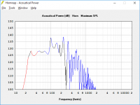
OK, reworked the box to have a <3:1 compression ratio (2.91:1). The box also worked out to be a bit smaller: 30"x22"x46"
The 18SW115-4 developed a big hump: the 18TBW100-4 modeled better (and is cheaper too).
Also, when modeling these B&Cs is it better to use Xmax or Xvar? I used Xvar.
The 18SW115-4 developed a big hump: the 18TBW100-4 modeled better (and is cheaper too).
Also, when modeling these B&Cs is it better to use Xmax or Xvar? I used Xvar.
Attachments
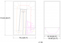
OK, reworked the box to have a <3:1 compression ratio (2.91:1). The box also worked out to be a bit smaller: 30"x22"x46"
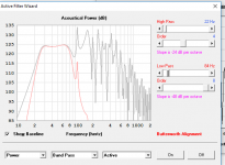
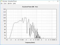
That huge 10dB spike right after the upper edge of the passband is something I'd try to avoid in a TH design
The one I bult has cone correction and didn't present the spikes, I supose it contributes to reduce that resonance in the upper range once the shape in front of the throat is heavier modified, but I never measured FR without it, so again, is a suposition, you might should deeper investigate

A little bit shorter, safer CR and more defined passband.
Getting closer. However the model you're using is not the "semi-inductance" one (which will require knowing and using the additional semi-inductance parameters). Because of this, the actual response of that build is likely to tilt a bit downwards at upper bass frequencies, the amount of tilt dependent on the driver's semi-inductance characteristics.
What sort of low-pass filtering are you planning to use with this TH?
I´m not planning to build that i´m only suggesting a design to KhrisKhad, and i think that the correct method is measure the driver when you got it, and then make the real design, to me all of this designs are only a little guide of how can the final design can be.
Filtering is not my fort.

Filtering is not my fort.
Attachments
It is not even mentioned as "compression ratio", let alone "CR".
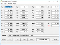
The value can however be read from the main Input Parameters window by moving the mouse pointer over S2 (for a tapped horn).
LOL! I always thought HR provided CR at S2 since the 1st time I used it.
Thanks for all the comments and information!
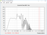
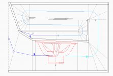
I've been playing with the design quite a bit. It has evolved to have an extended upper freq. response while losing a few Hz on the low end. It also has better efficiency and slightly better impulse response.
I changed the exit so it could have a larger L45 and S5.
I also extended the panel in front of the woofer so the cone "sees" a flat area, and part of it isn't firing directly down the path. This increased L23, which lowered the response and efficiency a bit.
Attachments
- Status
- This old topic is closed. If you want to reopen this topic, contact a moderator using the "Report Post" button.
- Home
- Loudspeakers
- Subwoofers
- 30Hz 18" Tapped Horn Design