Impedance Measurement
Here is a cheap and reasonably easy way if you have some alligator clips, some cable and a suitable resistor.
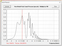
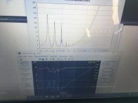
I would guess that the "honk" is resonances in the plywood walls of the large front resonator. How much bracing is there in the sides? There is quite a lof of pressure in the mouth and there are 8 parallell walls of 15 mm plywood that is prone to flexing if not braced enough. Below is a simulation of the mouth pressure a ROAR-in-progress with 400 watts of power in 2.0 Pi.
Here is a cheap and reasonably easy way if you have some alligator clips, some cable and a suitable resistor.
I would guess that the "honk" is resonances in the plywood walls of the large front resonator. How much bracing is there in the sides? There is quite a lof of pressure in the mouth and there are 8 parallell walls of 15 mm plywood that is prone to flexing if not braced enough. Below is a simulation of the mouth pressure a ROAR-in-progress with 400 watts of power in 2.0 Pi.
Attachments
‘Roar’ is really quite interesting! I’m very familiar with ‘paraflex’ in quite a few forms, and three one of my drivers in a ‘roar’ version of the tapped pipe with similar findings. One thing I noticed is (switching to a driver that will not perform in ‘paraflex’ ) the roar is a bit more hospitable to a variety of TS parameters, specifically the Bl^2/Re and maybe a little more friendly to those with mid 20s for an Fs ~Fb?
I could be off in my sim approach in HR, so I thought I would check in here?
My results are: if B&C 15sw115 in the topic roar of the thread I get this:
Impedance nulls at 38 and 78hz in 0.5xpi
Peak SPL at 108 hz is 109dB using 2.0 xPI and 2.83v
In 1.0xpi and rated power of 73.8v I get 141.1898 dB at 101hz Fb is 39hz
The cabinet is 276.836 liters
Really exciting cabinet and it seems to provide similar results to a paraflex. Which means a tapped pipe on steroids as far as I’m concerned.
Impedance Measurement
Here is a cheap and reasonably easy way if you have some alligator clips, some cable and a suitable resistor.
I would guess that the "honk" is resonances in the plywood walls of the large front resonator. How much bracing is there in the sides? There is quite a lof of pressure in the mouth and there are 8 parallell walls of 15 mm plywood that is prone to flexing if not braced enough. Below is a simulation of the mouth pressure a ROAR-in-progress with 400 watts of power in 2.0 Pi.
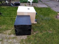
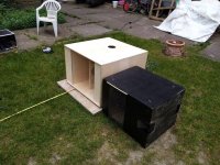
It is supported with very stiff bracing, also the backboxes of the cutout handles are braced against the wall and add extra stability. I was worried, if the backboxes could be a little to big (they sum up to ~5 liters) or causing irritation, but the simulation shows almost no difference.
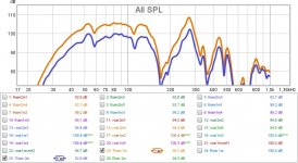
I set up the ROAR15 and a THAM15 in the garden today and did some quick 1m and 2m measurements. Sadly I could not measure impedance yet, but will buy a multimeter as soon as a recover financially (got fired because of COVID19
 ).
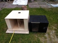
). The measurementsas shown below are not too reliable, i fear, since i could not move the subwoofers farther away from the house. The dip around 60hz present in both measurements seems to result from a reflection of the wall. wavelength at the given frequency calculates to almost exactly the distance I set them up. Also, due to the smaller size of the THAM, it hat a little more distance to the wall, so the dip should move down some 4 or 5 hz (as it does).
-> Will have to repeat the measurements at a friends site with more space.
At least, the initial impression of a somewhat honky sound did not rehappen, hence I suppose it was a matter of placement.
Attachments
Thank you for posting a direct comparrison like this, even if threre are some minor uncertainties it is still a comparable result which helps alot since far more diy'ers are famailliar with the THAM15 than the ROAR15.
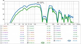
I'm a bit qurious about the ~110Hz dip only being present in the THAM15 since it is not iherit in it's response, any thoughts?
I'm very sorry to hear about your situation, these are strange, dificult and historic times, simply saying it sucks does not quite cover it.
Thank you / Anders
I'm a bit qurious about the ~110Hz dip only being present in the THAM15 since it is not iherit in it's response, any thoughts?
I'm very sorry to hear about your situation, these are strange, dificult and historic times, simply saying it sucks does not quite cover it.
Thank you / Anders
No idea about the 120hz dip. I do remember having the same issue the first time I measured the THAM, but it disappeared after inverting the phase. Hopefully, better measurements will give clarity on that. And also on the low end of the ROAR15, which I expected to be a bit stronger. According to the simulation it should be a little higher in the upper 40s range, right?
Ok, thats a bit strange, inverting the phase should not influence the response in this kind of meassurement (swept sine i asume), I would have guessed it's an artefact from the ROAR15 aperture being in close proximity, anyway, just qurious.
The ROAR15 has a longer path from front to back of driver so it should coupple lower than the THAM15, which I found becomes evident when applying some eq, it seems to respond well to this even below 40Hz, and in my expirience it should be a one or a couple of dB's up compared in the 50 Hz region compared to THAM15 and then the difference in sensitivity should increase in favour of the ROAR15 all the way up to the upper passband limit.
The ROAR15 has a longer path from front to back of driver so it should coupple lower than the THAM15, which I found becomes evident when applying some eq, it seems to respond well to this even below 40Hz, and in my expirience it should be a one or a couple of dB's up compared in the 50 Hz region compared to THAM15 and then the difference in sensitivity should increase in favour of the ROAR15 all the way up to the upper passband limit.
What are you using for a mic? I think I’ve git a similar cabinet here as a 170liter cabinet with a 12” driver 34/35 hz Fb.
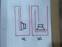
Is the roar design more like A or B here? Not much difference except ‘A’ might fit 2 drivers easier?
Is the roar design more like A or B here? Not much difference except ‘A’ might fit 2 drivers easier?
Attachments
Last edited:

So much changes here with the path lengths and coupling vs voids. Very tricky?, yet very fun to create the different types of these taped pipes and hybrids of them with added chambers along the way out. If I am at 35-40 hz and create a chamber that might mimic a heimholtz it bumps there in sim no doubt. Even if the idea was for a higher qw length for a low Fb and boost up higher if it’s outta steam too soon .
That rising rate of the roar seems to liven things up as deeper bass might have drown out kickdrums otherwise if a consistent lower beat exists in music. I have a similar response in two subs lijectgat and I almost did it too much and consider aiming a bit lower Fb and slightly less upper influence with the chamber so high up(more like the examples provided of roar.
Totally random thought but if my initial CSA in the long path is really small I get a bit of the tham15 response in that expanding greatly architecture. The dips shown at 60 and 120hz. or in cabinets with roar architecture but both paths are long and the longer is expanding greatky
Last edited:
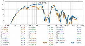
They both were side side by side while measuring? There might be your problem. When I compared tham15 and cubo15, there was strange dips in response because the other enclosure was resonating too and affected measurements!
So keep the area clear from any other subwoofers when measuring one
So keep the area clear from any other subwoofers when measuring one
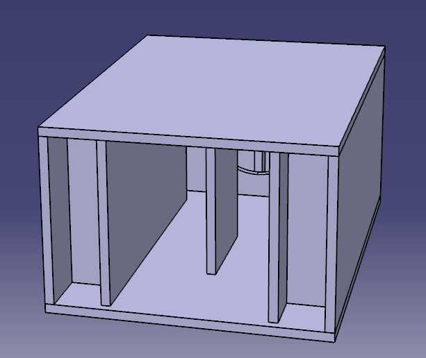
I believe (but I'm not sure) that perhaps the L45 depiction in your box plan sheet is more accurate, this since it might be so that only the fully enclosed volume is the one making up the QW resonator, and if so this is staring after the tapping (the openings into the resonator).
The question (and this was initially never fully resolved) is how the L34 transition should be set up, granted the L34 transition in the cad image might be slightly to long since the coupling (or summation) may not occur at the center of the driver, even though this is how you traditionally set it up.
I also see you adopt the advanced centreline method which has proven to be very accurate, in our case we let CATIA set up a natural flow line with neutral tension to describe the corner so we might loose some length there, I'm not sure which is best.
Hi Martinsson,
If building 2 X 10" ROAR. what would be the ideal distance between drivers, vertically and top/bottom distance panel to driver?
I'm sorry to say that I have not thought about that, I think one has the possibility to decrease the driver spacing somewhat compared to what would be the case if one simply doubled up on the dimensions.
The following reasoning is based upon a standard ROAR10 is oriented like this:
Then the inner height of the mouth would then be 334mm, and the driver cutout (diam. 230mm) is centered in the middle of this height.
The distance between the two driver cutout centers would be 334mm if you simply double up on the 334mm height, this I think may be a bit much.
If we instead keep the cutout edge-to-edge dimensions the same as in the standard roar10's cutout edge-to-end of baffle we would reduce the driver cutout center-to-center distance by 52mm arriving at 282mm.
With me so far? great.
This would then mean that the inner mouth height would be 616mm, whereas in the case of doubling up the standard roar10's dimensions this would be 668mm, leaving a gap between the edges of the two driver cutout edges of 104mm instead of 52mm.
All clear? perfect, let's continue.
The inner mouth height (being the same as the baffle height in this orientation) would then increase from 334mm to 616mm and the driver cutout centers would be 282mm apart and 167mm from the top and bottom baffle edges.
I'm not sure this is all correct, and it would need to be simulated to make sure the result is ok.
I'm sorry, I could have made this easier by writing the following instead:
Keep the driver cutouts edge-to-edge distance the same as the standard ROAR10's driver cutout edge to baffle edge distance (52mm).
This would give you a mouth height (baffle height) of 616mm in total for a dual driver version of the ROAR10.
But again, this needs to be simulated in order to see if my estimation is ok.
I'm sorry, I could have made this easier by writing the following instead:
Keep the driver cutouts edge-to-edge distance the same as the standard ROAR10's driver cutout edge to baffle edge distance (52mm).
This would give you a mouth height (baffle height) of 616mm in total for a dual driver version of the ROAR10.
But again, this needs to be simulated in order to see if my estimation is ok.
Yeah, this one is a lot simpler compared to the first reply you made. I did understand the first, but just took me quite a while.
I will try to sim 616mm and see the result.
Really appreciate your quick response, thanks.

Check the BOXPLAN-ROAR workbook at the following link to see how I tried to address it.
The Subwoofer DIY Page - Horn Folding
The Subwoofer DIY Page - Horn Folding
I've tried the BOXPLAN-ROAR and it's a great workbook especially if you are changing dimensions and panel thickness.
As for my question regarding the S3-S4 computation, I really didn't see the exact answers there. The only idea that I've seen as a basis for S3-S4 expansion was the driver basket height from baffle up to the point where it meets the magnet.
Will just cease the 2X10" ROAR build.
Thanks, Brian.
As for my question regarding the S3-S4 computation, I really didn't see the exact answers there. The only idea that I've seen as a basis for S3-S4 expansion was the driver basket height from baffle up to the point where it meets the magnet.
Will just cease the 2X10" ROAR build.
Thanks, Brian.
- Home
- Loudspeakers
- Subwoofers
- ROAR15