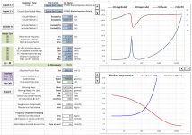
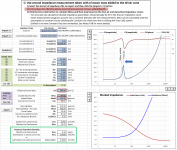
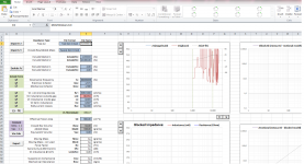
It may be a combination of a couple things. Looking at your imported data in Attachment #1, the resonance frequency for the added-mass measurement is essentially the same as for the free-air measurement. Do you know how much mass you added? You should see the resonance peak in the impedance measurement shift down in frequency. The "Vbox:" entry cell highlighted blue indicates that the added-mass measurement actually has resonance frequency slightly higher than free air, which is indicative of a closed box measurement....I'm thinking I've messed up the Semi Le calc process?
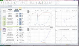
The other item that will need to be addressed is to update the values for cone area and added mass before you click the Vas Calc button. See Attachment #2 for excerpt of the directions and input cells identified.
Attachments
Many thanks for your assistance here Bolser.
And I promise I read the instructions twice. Seems I still missed adding the added mass and SD! Apologies.
So I retook my free air and Vas. I used 615 grams added mass. Have reloaded the two text files into the attached and updated SD.
The FS did not seem to budge with added mass. And the workbook now says my Vas is just 0.06L.
I've attached the output from DATS in PDF.
Apologies if I'm still messing this up. Please hang in there with me!
Cheers.
Attachments
No worries, we’ll get it figured out. ")
Looking at the internally saved data from the spreadsheet you posted, both the free-air and added-mass files contained exactly the same impedance data. I would guess that when you use the [Measure Vas] function in DATS, it measures the added-mas impedance, but doesn’t save it to the workbench data memory slot. So, when you click export again you are just saving another copy of the free-air data. I don’t own a DATS system, but I played briefly with the software without the DATS hardware connected. Here is how I would recommend collecting impedance data for use with Semi-Le_Calc.
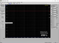
Step 1: Measure the Free-Air Impedance by clicking on the [Impedance Sweep] button.
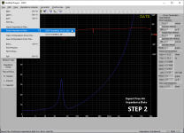
Step 2: Export the Free-Air Impedance data to *.txt or *.zma file.
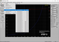
Step 3: Save the Free-Air Impedance data to Memory 1, so you can overlay it with the Added-Mass data.
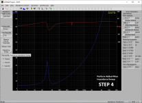
Step 4: Add your mass to the driver cone, and measure the Added-Mass Impedance by clicking on the [Impedance Sweep] button again. The resonance frequency should shift lower compared to the Free-Air impedance curve you saved. With 610g added, I would expect it to shift down near 15Hz. Except around resonance, the remainder of the curve should overlay the Free-Air curve.
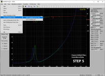
Step 5: Export the Added-Mass Impedance data to *.txt or *.zma file.
I think that should do it.
If anybody familiar with DATS has a better method please let us know.
Looking at the internally saved data from the spreadsheet you posted, both the free-air and added-mass files contained exactly the same impedance data. I would guess that when you use the [Measure Vas] function in DATS, it measures the added-mas impedance, but doesn’t save it to the workbench data memory slot. So, when you click export again you are just saving another copy of the free-air data. I don’t own a DATS system, but I played briefly with the software without the DATS hardware connected. Here is how I would recommend collecting impedance data for use with Semi-Le_Calc.
Step 1: Measure the Free-Air Impedance by clicking on the [Impedance Sweep] button.
Step 2: Export the Free-Air Impedance data to *.txt or *.zma file.
Step 3: Save the Free-Air Impedance data to Memory 1, so you can overlay it with the Added-Mass data.
Step 4: Add your mass to the driver cone, and measure the Added-Mass Impedance by clicking on the [Impedance Sweep] button again. The resonance frequency should shift lower compared to the Free-Air impedance curve you saved. With 610g added, I would expect it to shift down near 15Hz. Except around resonance, the remainder of the curve should overlay the Free-Air curve.
Step 5: Export the Added-Mass Impedance data to *.txt or *.zma file.
I think that should do it.
If anybody familiar with DATS has a better method please let us know.
Attachments
Last edited:
Yes that did it nicely - wonderful powers of deduction Bolser!
I did just as you recommended except I created two exports. One for the vanilla free air sweep, the second as another free air sweep but with the added 610 grams of mass.
So I didn't add the first to memory, then, and export the two as one file.
The difference this time was that my second measurement wasn't done using the "Measure V(as)" function in DATS. This doesn't seem to remeasure the impedance, explaining why my first attempts at the "added mass" sweep (which one would normally do using this "Measure V(as)" function) didn't get the desired data for the Semi Le workbook.
My bad entirely then!
Now I have a very reasonable Vas of 121L and you were spot on with your estimate of 15hz with that much mass added.
Thank you!
Attachments
Last edited:

FDD Error
Hi Bolser,
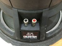
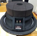
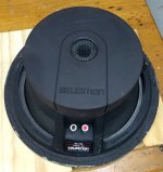
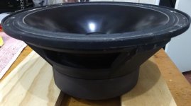
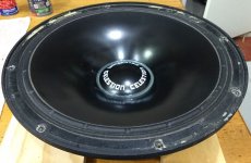
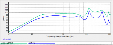
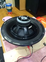
I have rescued an old Celestion AD15H from the boot of my car as I wanted to see how it would model in the tapped horn I will be building for the Alpine SWS15D4.
I have owned this driver for 26 years and pounded on it in my car for all that time. It deserves better!
It sure models nice with Semi-Le enabled...

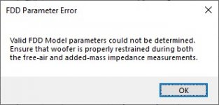
When I try to calculate Vas I get an FDD error - see attached.
Not sure what I'm doing wrong. Very much hoping for some more help please.
Thank you.
Cheers.
Hi Bolser,
I have rescued an old Celestion AD15H from the boot of my car as I wanted to see how it would model in the tapped horn I will be building for the Alpine SWS15D4.
I have owned this driver for 26 years and pounded on it in my car for all that time. It deserves better!
It sure models nice with Semi-Le enabled...
When I try to calculate Vas I get an FDD error - see attached.
Not sure what I'm doing wrong. Very much hoping for some more help please.
Thank you.
Cheers.
Attachments
-
Celestion AD15H DATS T&S Data.pdf316.3 KB · Views: 88
-
 FDD Error.jpg17 KB · Views: 64
 -
 AD 15H Inputs.jpg84.2 KB · Views: 69
 -
 AD 15H Back2.jpg89.4 KB · Views: 64
 -
 AD 15H Back1.jpg87.2 KB · Views: 115
 -
 AD 15H Side1.jpg41.9 KB · Views: 71
 -
 AD 15H Top1.jpg68.5 KB · Views: 108
 -
Semi-Le_Calc_V3 Celestion AD15H.zip1.3 MB · Views: 68
-
 BP MTH Alpine vs Celestion.png8.6 KB · Views: 446
Last edited:
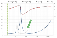
Could be wrong, but my guess is that the mass is not firmly attached to the cone resulting in some decoupling and secondary resonance peaks. It could also be that the woofer was not firmly restrained during the measurement. Can you describe how you attached the mass to the cone and how you restrain the woofer during measurement?...When I try to calculate Vas I get an FDD error - see attached
Attachments
Gents,
Thanks for your thoughts. I like the magnets and dough ideas Mark. I'll need to source these to try again.
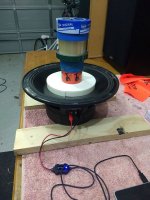
Bolser, again thanks for your guidance. I did try a few different approaches that normally I have no problem with - a stack of different masking tapes. These are usually work well with the tacky side sitting securely against the cone.
With the Celestion AD 15H having a 4" VC the dust cap is large enough for me to take some extraordinary steps. See images. Nothing seemed to solve the FDD issue. I did go all the way out to 2.2 kgs added mass with a 10" driver and still I got the FDD.
Some files attached for your information.
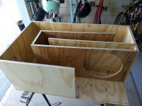
Nevertheless my 4th tapped horn - I'm calling it the BP-MTH-266 - is under construction. And I'm excited!
Many thanks for this wonderful tool. It has really given me that extra level of confidence in my HornResp modeling.

Thanks for your thoughts. I like the magnets and dough ideas Mark. I'll need to source these to try again.
Bolser, again thanks for your guidance. I did try a few different approaches that normally I have no problem with - a stack of different masking tapes. These are usually work well with the tacky side sitting securely against the cone.
With the Celestion AD 15H having a 4" VC the dust cap is large enough for me to take some extraordinary steps. See images. Nothing seemed to solve the FDD issue. I did go all the way out to 2.2 kgs added mass with a 10" driver and still I got the FDD.
Some files attached for your information.
Nevertheless my 4th tapped horn - I'm calling it the BP-MTH-266 - is under construction. And I'm excited!
Many thanks for this wonderful tool. It has really given me that extra level of confidence in my HornResp modeling.
Attachments
Last edited:
Thanks for clarification on your current testing methods. Yeah, it looks like relying on tackiness of tape to attach that much weight to a cone is resulting in some decoupling and the multi-resonance points you are experiencing. You might try using less weight instead of more. Alternatively, using magnets like mwmkravchenko mentioned works great on most cones, although you have to be careful with aluminum cones to avoid dents when the magnets suddenly click towards each other from opposite sides of the cone.
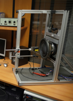
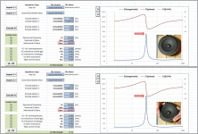
Likewise, for improved accuracy of Qms and FDD values, you would need to restrain the woofer during the measurement. Ideally it would be mounted with the cone oriented vertically and the magnet system held in a vise or clamp of some kind to a frame or bench of substantial mass. For DIY, you can get pretty close by firmly holding the woofer down by the frame. Attached is an example of what to expect. The more firmly you hold the woofer, the lower the losses imparted to the entire resonance system(woofer + restraint) and the higher the magnitude of the impedance peak. Note that Qms is the only TSP that is significantly changed. Ideally the restraint system would be infinitely stiff, so the only losses you would be measuring would be due to the woofer suspension. This is what Qms is supposed to be…a measure of the woofer suspension losses. The FDD model takes this one step further by modeling the frequency dependence of these losses. But, it requires good quality data taken with firmly restrained woofer and firmly attached added mass.
As mentioned back in Post #30, the FDD parameters are not required for accurate frequency response modeling like the Semi-Le parameters are. The FDD will, however, significantly improve the predictions of the magnitude of the different impedance peaks in a woofer + enclosure system.
Attachments
Last edited:
Alternatively, using magnets like mwmkravchenko mentioned works great on most cones, although you have to be careful with aluminum cones to avoid dents when the magnets suddenly click towards each other from opposite sides of the cone.
I learned that the hard way. Some metal cone drivers have very thin cones. I use ferrite magnets. I never found that a very thin metal cone sounded great. And in personal design work I generally spec metal cones that are thick enough to be tough to dent. This has an added benefit of cleaning up the midrange significantly.
Hmmm....maybe not as strange as it appeared...I have a theory.
Note the software requirements include having the "Analysis Tool Pak" and "Solver" add-ins installed and active. Did you do this before running V2? If not, V1 of the spreadsheet checks to see if this is the case, and if not it attempts to activate them for you. Once active in your installation of Excel, they stay active unless you intentionally go and de-select them. V2 of the spreadsheet did not have this auto-activation feature. The reason I removed it was that it only worked if installation language was English. If it wasn't English it would give errors even when the required add-ins were installed and active. So, the spreadsheet was essentially unusable for non-English installations. I was unable to figure out a way around this problem, so removed it. I'm guessing that is what was going on.
V3 which I'm close to posting, will have some additional details on how to install and activate the required add-ins. It will also have a button to click for English installations that will do the activation for you. So, not fully auto-activation, but close for English installations, and will avoid problems with non-English installs. In addition to that, V3 will add FDD(Frequency Dependent Damping) parameters that Hornresp also includes a model for.
Hi Bolserst,
I have a non-English installation of Excel. I get a runtime error 9 when checking for analysis toolpak and the solver add-in. I activated both of these add-ins. When I try to import an impedance graph, I get jibberish data and plot. What should I do?
Best,
Selim
Hi Bolserst,
I have a non-English installation of Excel. I get a runtime error 9 when checking for analysis toolpak and the solver add-in. I activated both of these add-ins. When I try to import an impedance graph, I get jibberish data and plot. What should I do?
Best,
Selim
EDIT: I installed the English version of Excel. Now "Check Analysis Toolpak" works, but "Check Solver Add-in" returns a "Runtime Error '9'" "Subscript out of range" error. When I try to import the impedance graph, again I get the same strange graph and data. Macros are active, both add-ins are active.
The txt file (attached) seems ok and it comes straight from DATS.
Attachments
Last edited:
Thanks for posting the screenshot of your spreadsheet after importing the DATS data file.
It appears that your system decimal separator is set to "," and thousands separator to "."
Decimal separator - Wikipedia
Other countries use "." for the decimal separator.
Unlike the metric system the world looks a bit more evenly split on this one.
As long as your system setting matches the data files you are reading in, it should work fine.
It looks like the DATS file you posted was exported using a decimal separator of "."
Attached is a version with the decimal separator switched to ","...see if you can read it in.
Alternatively, you can change the system settings instead of the data file.
Change the Win-7 thousand separator (distinction) and decimal symbol
I'm not sure about the "Runtime Error '9'", will have to do a little more research on that and report back.
Attachments
Last edited:
So thanks to Steve, the worksheets are running. After I import the impedance file, the T/S parameters that show up on the worksheet before I do the LS-fit are not the same as what DATS has come up with. Some values are very close, some values are quite a bit off. Am I doing something wrong? Shouldn't the values agree?
I have the Vas value (from the specs) at hand so I opted to enter that manually as opposed to creating a new weight added .zma. So after I enter Vas and hit LS-fit, the regular Qes, Qms and Le values change drastically. See comparison chart below:
DATS Value Semi-Le_Calc Semi-Le_Calc (fitted)
Qes 0,28 0,26 1,00
Qms 8,65 8,15 17,56
Le 1,28 2,44 1,19
Is this normal? Am I doing something wrong?
I attached the *.zma file and screenshots of the worksheet.
Attachments
No, you are not doing anything wrong. This is a further complication of the different decimal separator you are using. The limits set in the Solver for the different parameters assume a “.” decimal separator. I see a few postings on Excel forums with people having similar issues. I have an idea of how to code around the problem. In the mean time as a work around, before running the LS-fit set the system decimal separator to “.” and the thousands separator to “,”. Set them back when complete. Details on how to do this can be found at Link in Post #75. As an example, I went thru this process with your data file and the results are shown in the attached pic.
For anybody else who is having problems activating the Solver Add-in, I found out that in some installations(like portakalx2's) the Solver Add-in doesn’t actually install(even though all the boxes are checked that it is) until it is used for the first time manually in the spreadsheet. For those interested, more details can be found here: Using Solver in Excel VBA. In the next revision, I will add some details in the *.pdf file how to do this. Next revision will also be able to read in Unix/Linux ASCII files(ie no carriage returns), and hopefully fix the LS-fit limits issue with “,” decimal separator.
For anybody else who is having problems activating the Solver Add-in, I found out that in some installations(like portakalx2's) the Solver Add-in doesn’t actually install(even though all the boxes are checked that it is) until it is used for the first time manually in the spreadsheet. For those interested, more details can be found here: Using Solver in Excel VBA. In the next revision, I will add some details in the *.pdf file how to do this. Next revision will also be able to read in Unix/Linux ASCII files(ie no carriage returns), and hopefully fix the LS-fit limits issue with “,” decimal separator.
Attachments
Last edited:
The Wright inductance model seems to be a previous attempt at approximating a driver's frequency-dependent inductance for sim purposes. For that, the following parameters are defined:
Krm
Erm
Kxm
Exm
Is there a fairly easy way to translate from the Wright parameters to the semi-inductance parameters given in your spreadsheet, or are the models just to different to be able to do so?
Krm
Erm
Kxm
Exm
Is there a fairly easy way to translate from the Wright parameters to the semi-inductance parameters given in your spreadsheet, or are the models just to different to be able to do so?
Is this for a driver that the tabulated impedance data is no longer available?
Do you know what software was used to generate the Wright parameters?
I'm not sure if there is a closed form solution to calculate Semi-Le parameters directly from the Wright model parameters. But, could certainly calculate impedance based on entered Wright parameters and then run the fit routine to get the Semi-Le parameters that best match. I will take a look, see what can be done to incorporate.
- Home
- Loudspeakers
- Subwoofers
- Semi-Le_Calc: Calculator for Advanced Inductance Model Incorporating Semi-Inductance